
A signal injector consists of a circuit that generates an audio frequency for testing in amplifier circuits and radios. By injecting the signal from this circuit into a radio or an amplifier, we can check whether it is working or not. Your signal should be played as a whistle on the unit's speaker.
To find out where the fault is in a circuit we are injecting the signal from the loudspeaker to the input of the circuit to the point where the signal disappears. When this happens, it is because we come to the stage with problems.
We must then check the state of the components of this step.
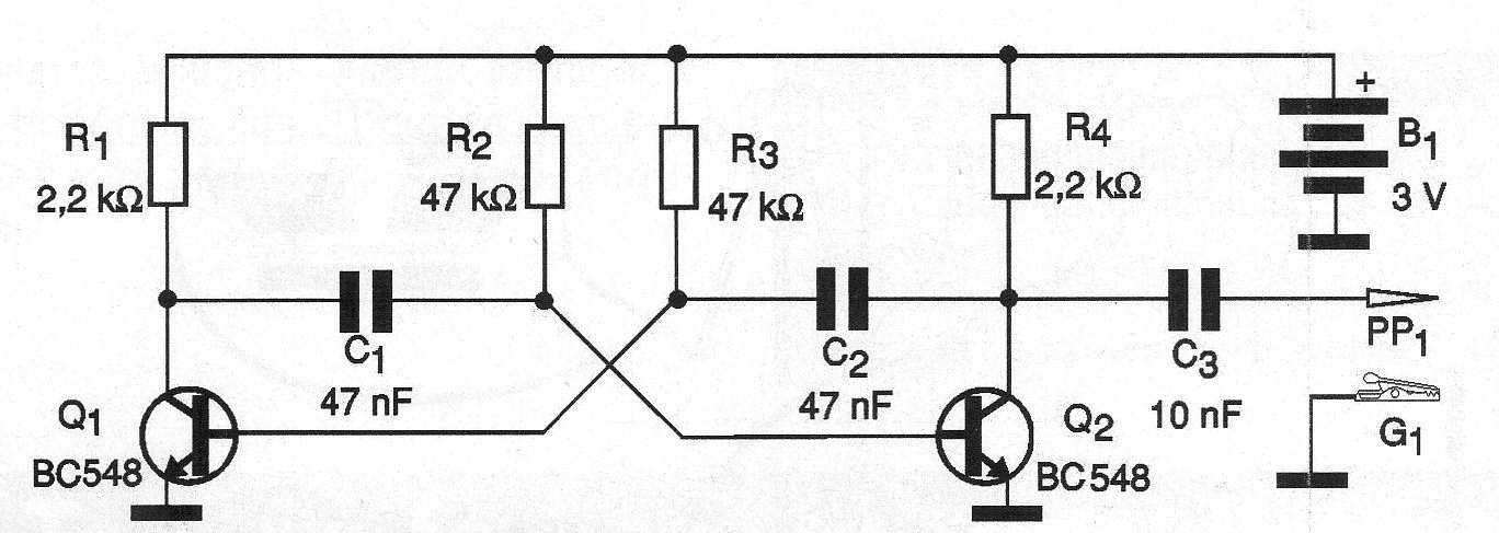
Our circuit consists of an astable multivibrator with two transistors mounted based on a terminal strip, so that the assembly is as simple as possible.
The injector diagram is shown in figure 1.
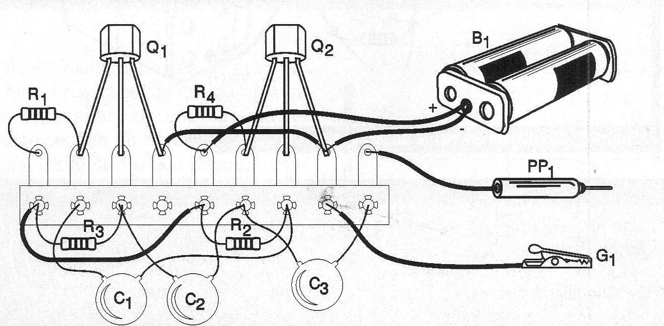
The mounting is shown in figure 2. It is clear that the most skilled readers can do the assembly in protoboard or printed circuit board.
Material
Q1, Q2 - BC548 or equivalent - general purpose transistors
R1, R4 - 2.2k ohm x 1/8 W - resistors - red, red, red
R2, R3 - 47 k ohm x 1/8 W - resistors - yellow, violet, orange
C1, C2 - 47 nF - ceramic or polyester capacitors
C3 - 10 nF - ceramic or polyester capacitor
B1 - 3 V - 2 small batteries
PP1 - probe
G1 - Alligator Clip
Miscellaneous:
Terminal bridge, two battery holder, mounting box, wires, solder, etc.


