
We can show how an operational amplifier works by mounting a simple circuit with the 741. The circuit can be implemented in a solderless board.
In Figure 1 we then have the circuit for the experiment. Other operating amplifiers may be used, only the terminal arrangement should be observed.
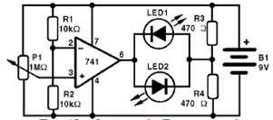
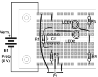
In the experiment, from the position of least resistance one of the LEDs is lit and the other one is off. We then turn the potentiometer to the moment we reach the reference voltage given by R1 and R2. At this point, the operation switches. With this, one of the LEDs goes out and the other lights up.
The potentiometer must be pre-prepared to have three connecting wires that fit into the contact array.
Material list
CI-1 - 741 - operational amplifier
LED1, LED2 - Common red or other colored LEDs
R1, R2 - 10k ohm x 1/8 W- resistor - brown, black, orange
R3, R4 - 470 ohm x 1/8 W - resistors - yellow, violet, brown
P1 - 1 M ohm - lin or log potentiometer
B1 - 9 V - battery or power supply
Miscellaneous:
Matrix of contacts, battery connector, wires, etc.


