
Interesting toys can be made with motors and electronic circuits. An example of this can be given by radio controlled toys that we have published several times.
What we propose is the assembly of an electronic boat, whose engine is controlled by a time circuit. This boat walks and stops at regular intervals and will still flash a warning light.
The setup of the time circuit is very simple, serving as training for beginners who, after that, can go to more complex projects, such as a radio controlled boat.
The boat can be a plastic one of the type found ready in toy stores or improvised with a styrofoam.
How it works
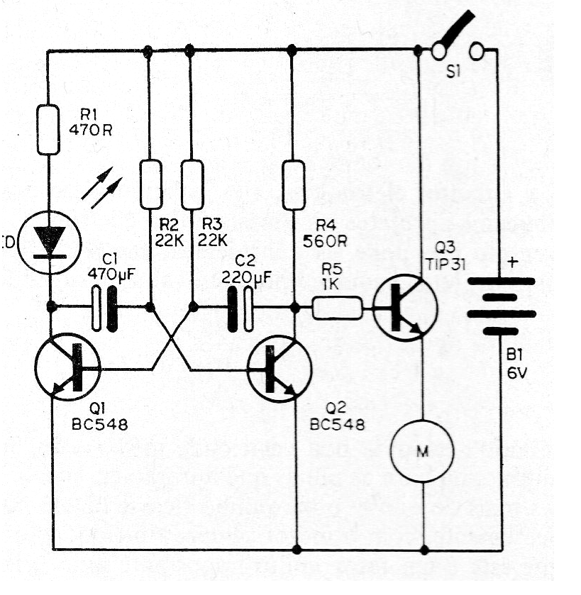
To turn the motor on and off intermittently we use an oscillator called astable multivibrator. In this circuit we have two transistors that function as switches on and off alternately at intervals depending on the capacitors connected at their bases.
If we use two capacitors of different values the times of stop and movement will also be different. In the project we chose capacitors to have stop time a little higher than the drive.
The multivibrator controls a 6 V motor through a power transistor. The motor can be obtained from some old-fashioned battery toy.
Assembly
We have two phases of the assembly to be considered: the preparation of the boat and the assembly of the electronic part.
As plastic toy boats are made of soft material, the preparation work is simple, as shown in Figure 1.
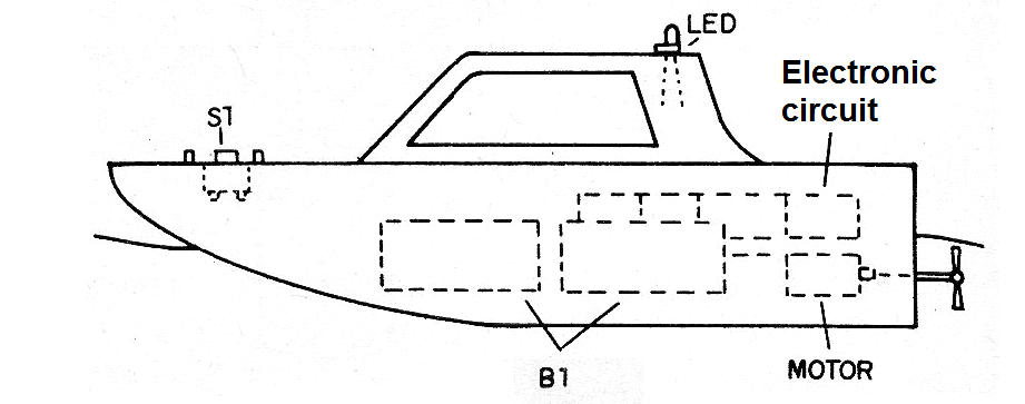
All you have to do is drill the top of the plastic and put the key that will turn the circuit on and off (S1). Another hole, in position that must be chosen as the boat is for the LED. Battery, engine and electronic circuit support will be inside the boat. Toy boats will already have the engine set to power a propeller.
Turning to the electronic part, we give the complete circuit in figure 2.
In figure 3 we have the welding of the main components in a terminal bridge. Make sure the boat has enough space for your installation.
33Figure 3 - Terminal strip assembly
Look carefully at the positions of the components. If you turn the engine "reverse" when turning the motor on, reverse its connecting wires. Electrolytic capacitors can be changed to change drive times.
Material list
Q1, Q2 - BC548 or equivalent - general purpose NPN transistors
Q3 - TIP31 - NPN power transistor
LED - common LED of any color
C1 - 470 uF x 6 V or more - electrolytic capacitor
C2 - 220 uF x 6 V or more - electrolytic capacitor
R1- 470 ohms x 1/8 W - resistor - yellow, violet, brown
R2, R3 - 22k x 1/8 W - resistor - red, red, orange
R4 - 560 ohms x 1/8 W - resistor - green, blue, brown
S1 - Single switch
B1 - 6 V - 4 small batteries
Miscellaneous: terminal strip, battery holder, wires, solder, etc.


