
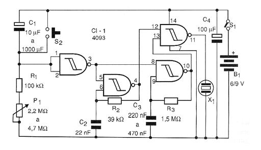
The circuit shown in the figure works as follows: when the power is turned on it remains inactive until at the end it beeps through the transducer. The principle of operation is the same, except that when the power is switched on, the capacitor maintains the high level at the input of the first port of the 4093 to the point set by P1.
Intervals that can reach more than 1 hour are achieved with the maximum values of the indicated components. The tone and the flashing of the circuit depend on R3 and R4 that can be changed over a wide range of values. The consumption of the device is very low in the standby condition, being less than 1 mA. To reset the circuit and start a new timer, simply press S2 for a moment.
Material list
CI-1 - 4093 - CMOS integrated circuit
R1 - 100 k ohm x 1/8 W - resistor - brown, black, yellow
R2 - 39 k ohm x 1/8 W - resistor - orange, white, orange
R3 - 1.5 M ohm x 1/8 W - resistor - brown, green, green
P1 - 2.2 M ohm at 4.7 M ohms - lin or log potentiometer
C1 - 10 uF to 1 000 uF x 12 V - electrolytic capacitor - see text
C2 - 22 nF - ceramic or polyester capacitor
C3-470 nF at 1 uF - polyester capacitor
C4 - 100 uF x 12 V - electrolytic capacitor
S1 - Single switch
S2 - Pressure switch NA
B1 - 6 or 9 V - 4 batteries or battery
X1 - High impedance piezoelectric transducer
Several:
Printed circuit board, battery holder or battery connector, wires, button for P1, solder, etc.


