
People living near medium-wave radio stations may suffer from the drawback of having their emissions affecting sound equipment, radios from other bands, telephone lines and even televisions.
With the filter described, we eliminate the signal from these stations by tuning them into a variable so that they are rejected.
The filter rejects a single frequency of the medium wave range and can be used with medium wave, shortwave, TV, FM, and telephone lines being interleaved between the antenna and the input of the interfering device or in series with the line.
Another installation location is between the cable through the signal, for example into a stereo, and the amplifier.
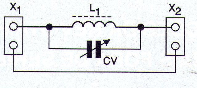
In figure 1 we have the complete diagram of the filter.
In figure 2 we have the aspect of the assembly that should be fit into a small box, preferably of metal, to serve as a shield.
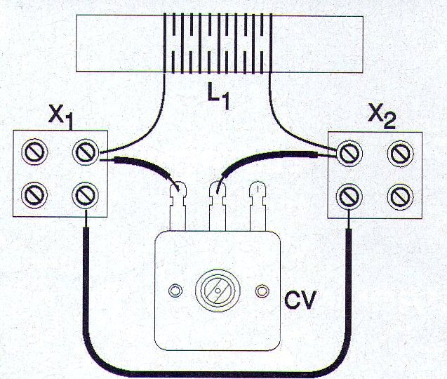
The coil L1 is formed from 80 to 100 turns of enamelled wire between 24 and 30 AWG which are wound on a ferrite rod of 0.8 to 1 cm in diameter and 10 to 20 cm in length.
The CV capacitor can be any common variable used in medium or short-wave radios with maximum capacitance in the range of 150 to 300 pF.
Antenna / ground terminals are used for the output of the filter or according to the antenna cables of the interfering device.
To use the device, only insert it between the antenna and receiver (grounding is important) and adjust CV so that the unwanted signal is rejected.
MATERIAL LIST
L1 - Coil - see text
CV – variable capacitor from 150 to 300 pF - see text
X1, X2 - antenna / ground type terminals
Miscellaneous:
Ferrite stick, mounting box, button for variable, enameled wires, wires, solder, etc.


