
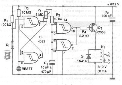
In the circuit of the figure we used two of the 4093's ports as a bistable and the other two in a time circuit, thus obtaining a delayed alarm. After the sensor X1 has been activated for an instant, the capacitor C1 charges slowly for a time set at P1 until the last two ports of the 4093 change state by activating the relay K1. The alarm connected to the relay trips.
To reset, turn off the alarm or press the reset sensor momentarily and wait for C1 to discharge until the alarm stops ringing. In the standby condition, the consumption of this alarm is very low which allows its power to be made by batteries or battery.
The relay is chosen according to the supply voltage and must have a coil current of max. 50 mA. Several sensors can be connected in parallel for the protection of several points. The capacitor C1 that determines the delay can have values in the indicated range and the fine adjustment is made in P1. The assembly can be easily carried out in a contact array or printed circuit board.
Material list
CI-1 - 4093 - CMOS integrated circuit
Q1 - BC558 - general purpose PNP transistor
D1 - 1N4148 - general purpose diode
K1 - 6 or 12 V relay - see text
X1 - sensor type NA (reed, microswitch, etc.)
X2 - Touch sensor or NO switch
R1 - 100 k ohm x 1/8 W - resistor - brown, black, yellow
R2 - 10 M ohm x 1/8 W - resistor - brown, black, blue
R3 - 10 k ohm x 1/8 W - resistor - brown, black, orange
R4 - 2.2 k ohm x 1/8 W - resistor - red, red, red
P1 - 1 M ohm - trimpot or potentiometer
C1 - 10 uF to 470 uF x 12 V - electrolytic capacitor
C2 - 100 uF x 12 V - electrolytic capacitor
Several:
Solderless board or printed circuit board, power supply or batteries, battery holder or connector, wires, solder, etc.


