
This oscillator can produce a high frequency signal in the range of 20 MHz to 150 MHz, depending only on the used coil and the capacitor C2. There are several possible applications such as remote control transmitters, signal injectors or wireless microphones.
The circuit has only one transistor whose oscillation frequency is determined by L1 and CV. We can have several coils according to the desired frequency range, as shown in the table below:
20 MHz at 50 MHz - 9 turns of wire 24 - C2 = 47 pF
50 MHz at 80 MHz - 6 turns of wire 24 - C2 = 39 pF
80 MHz at 110 MHz - 4 turns of wire 24 - C2 = 10 pF
110 MHz at 150 MHz - 2 turns of wire 24 - C2 = 2.7 pF
C2 must be ceramic and the power is made with 4 small batteries or a 9 V battery. The resistors are 1/8 W.
To use the unit and check for oscillation using an FM radio as a monitor or to tune to the desired range. The frequency setting is in CV.
Remember that only the carrier is heard in the form of a wheezing when tuning the frequency of this oscillator, since there is no modulation.
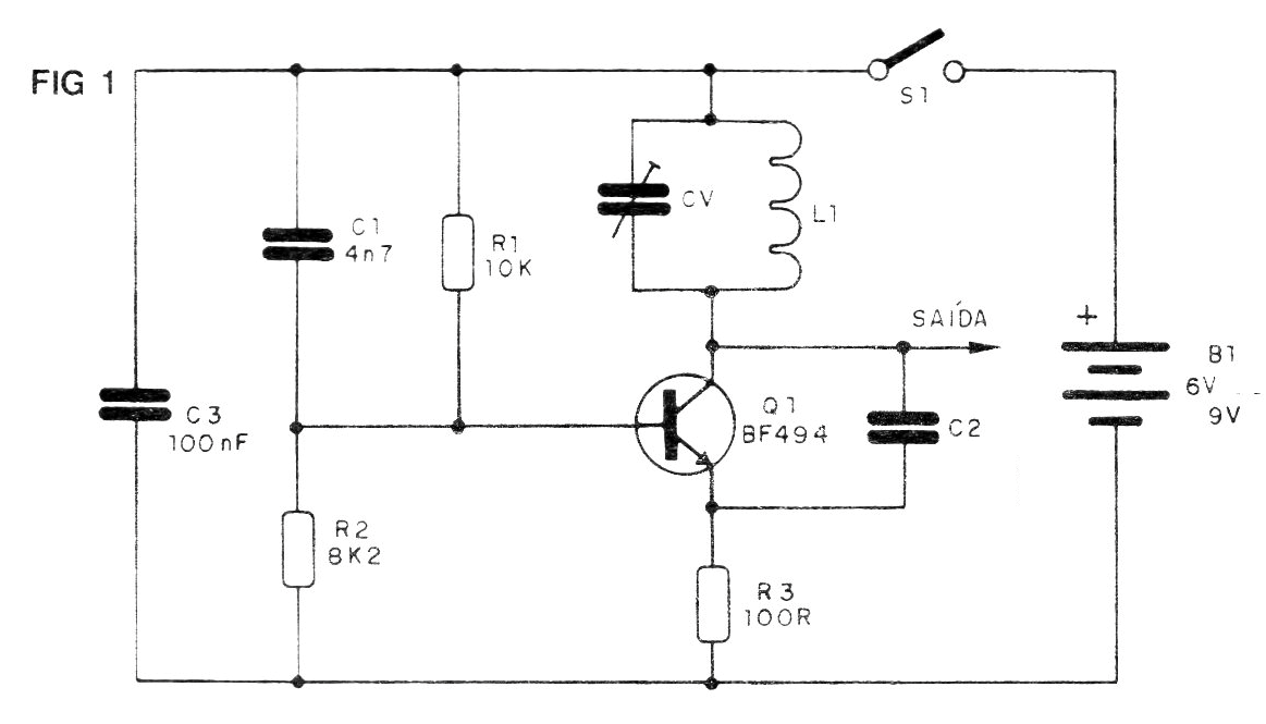
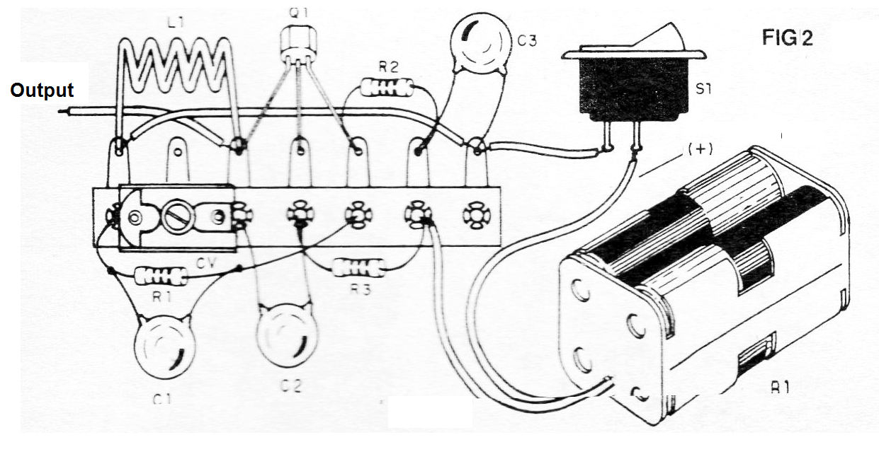
Material list:
Q1 - BF494 or equivalent - RF transistor
L1 - Coil - see text
CV- trimmer of 2-20 pF or close to that
C1 - 4.7 nF - ceramic capacitor
C2 - see text
C3 - 100 nF - ceramic capacitor
R1- 10 k ohm - resistor (brown, black, orange)
R2 - 8k2 - resistor (gray, red, red)
R3 - 100 ohm - resistor (brown, black, brown)
S1- Single switch
B1 - 6 or 9 V - batteries or battery
Miscellaneous:
Terminal bridge, battery holder or battery connector, wires, solder, etc.


