
This circuit, quite simple by the way, is for testing capacitors of all types in the range of 10 nF to 100 uF (more or less), providing a sound indication. If you do not have the resources to test if your capacitors are good you should not fail to mount this fitting.
The basic idea is very simple: an oscillator whose feedback and thus frequency of the sound it produces is determined by a capacitor. We put a good capacitor in the circuit and it works, causing the speaker to whistle or emit crackling (depending on the value). If the capacitor is bad (open or short) there is no feedback and the oscillator does not work.
Since the frequency of the sound depends on the value of the capacitor, with a little training and the use of capacitors of known values for comparison, we can find out the value of the capacitor tested.
The circuit operates with voltages of 3 or 6 V, (two or four batteries) and is very simple to assemble.
How it works
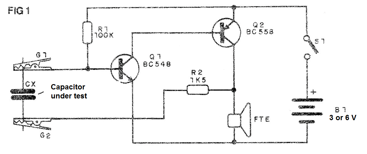
As we have explained, it is an oscillator whose frequency is determined by the capacitor and also by the resistor R1 that controls the polarization of the transistor.
It is convenient for R1 to be in the range of 100k to 470k if most of the tests are for small capacitors (10nF or near). And that is in the range of 10k to 56k if the capacitors tested are more than 1 uF. A little bit can be added to switch the resistor.
The oscillator's complementary transistors provide good power to the audio signal applied to the speaker. See that the sound will be the more acute the smaller the capacitor.
Assembly
In figure 1 we have the complete diagram of the tester.
In figure 2 we have the assembly on a terminal strip. This strip can be installed in a plastic box with claw wires to test the capacitors.
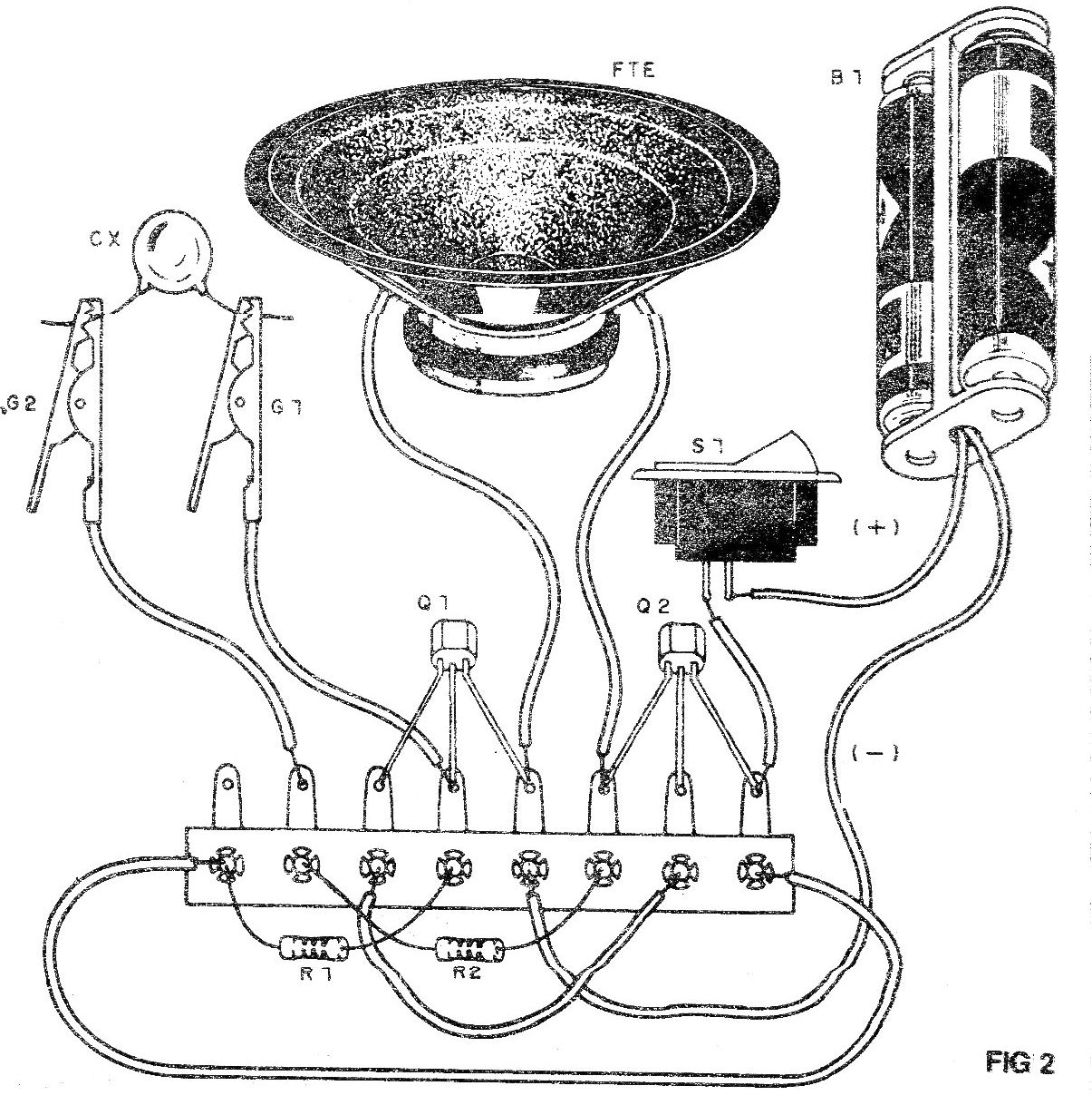
A switch can be added to turn the unit on and off. The transistors may be of any general NPN or PNP type of use as the case may be.
Test and Use
Simply plug the unit in and place the test leads on the capacitor under test.
The lower its value, the higher the sound emitted if it is good.
For capacitors above 1 uF the sound will be formed by interval pulses.
Material list
Q1 - BC548 or equivalent - NPN transistor
Q2 - BC558 or equivalent - PNP transistor
FTE - 8-ohm speaker
B1 - 3 or 6 V- 2 or 4 small batteries
R1- 100k ohm - resistor (brown, black, yellow)
R2 - 1k5 ohm - resistor (brown, green, red)
Miscellaneous: terminal strip, battery holder, alligator clips, mounting box, wires, solder, etc.


