
The circuit shown in figure 1, activates a bar of 4 LEDs with an audio signal applied to its input.
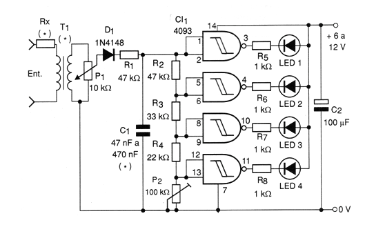
The resistors in series with the LEDs determine their brightness and can be reduced if the supply voltage is less than 9 V.
The capacitor C1 determines the inertia of the system, ie the speed at which it responds to variations of the input audio signal.
The transformer serves to isolate the audio circuit from the bargraph. Any small power transformer that has a primary winding for the power grid (which will be connected to the potentiometer) and a secondary one from 3 to 9 V with current in the range of 50 mA to 250 mA can be used.
The potentiometer is used to set the operating point of the movable bar indicator according to the intensity of the input signal.
The 100 k ohm trimpot is used to adjust the scale so that all LEDs are off in the absence of a signal. In fact, this trimpot adjusts the scale extension.
The circuit can be adapted to operate with 2 4093 and thus drive up to 8 LEDs on a scale. In this case, the input resistor network must be adapted.
For more LEDs, however, the supply voltage should be between 9 and 12 V.
In figure 2 we give a printed circuit board for the assembly of this circuit.
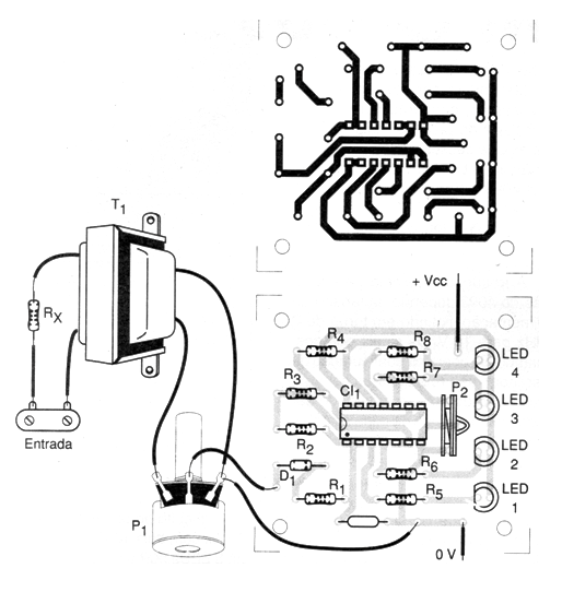
The primary of the transformer is connected to the speaker output of the stereo. Rx depends on the power of the sound equipment, according to the following table:
Power Rx
up to 5 W 10 ohms x ½ W
5 to 20 W 22 ohms x ½ W
20 to 50 W 47 ohms x 1 W
50 to 100 W 100 ohms x 1 W
More than 100 W 220 ohms x 1 W
Material list
4093 - CMOS integrated circuit
LED1 to LED4 - Common red LEDs
D1 - 1N4148 - general purpose diode
R1, R2 - 47 k ohms x 1/8 W - resistors - yellow, violet, red
R3 - 33 k ohms x 1/8 W - resistor - orange, orange, red
R4 - 22k ohms x 1/8 W - resistor - red, red, orange
R5 to R8 - 1k ohms x 1/8 W - resistors - brown, black, red
Rx - see text - resistor depending on the power of the sound equipment
P1 - 10 k ohms - potentiometer
P2 - 100 k ohms - trimpot
C1 - 47 nF to 470 nF - ceramic or polyester capacitor
C2 - 100 uF x 12 V - electrolytic capacitor
T1 - Transformer - see text
Several:
Printed circuit board, power supply, mounting box, wires, solder, etc.


