
We present an experimental circuit with only two transistors which, powered by batteries can cause neon or fluorescent lamps to flash at a frequency that can be set to 1 every minute up to 10 per second. The circuit is simple and can be used in demonstrations or for signaling.
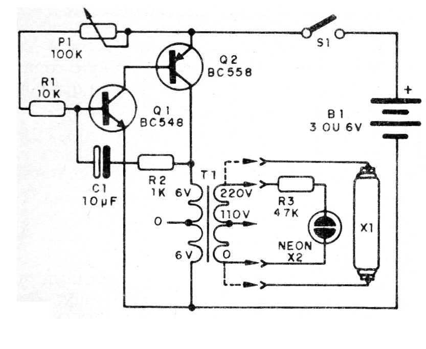
The basic idea of this design is a low frequency oscillator that produces pulses. These pulses applied to a transformer have their voltage raised to the point of being able to excite fluorescent or neon lamps. These lamps need at least 80 V to light up.
Of course the pulses are of small energy, but the luminous flash obtained can be observed with ease, which makes possible the use of the device in signaling.
The interesting thing about the circuit is that we can supply it with voltages from 3 V and even from 9 to 12 V with the use of transistor TIP32 to Q2 with pulses of much greater intensity. In figure 1 we have the complete diagram of the apparatus.
The arrangement of the components on a terminal strip is shown in figure 2.
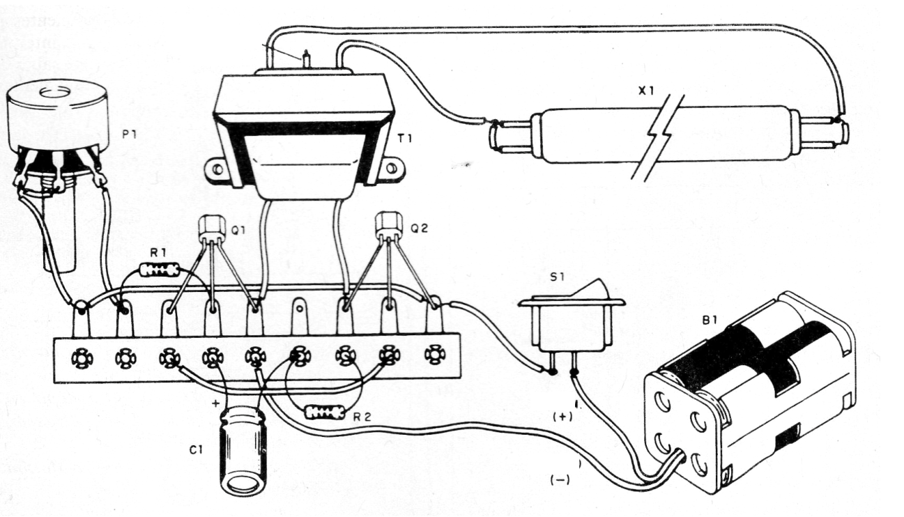
The transformer is of the type used in primary power supplies of 110 V or 220 V and secondary of 5 to 12 V with current of 100 to 500 mA. We will connect the 110 V or 220 V winding to the neon lamp or the fluorescent lamp.
The wires for the lamp may be long, but they must be insulated since the high voltage can cause shocks to touch them. The other components are common and the capacitor that determines the frequency can have values of 1 uF to 10 uF. Transistors allow equivalents and for larger voltages use BD136 or TIP32 for Q2.
The fluorescent light does not need to be new. Even weakened lamps that no longer work in the power grid will light up in this circuit. These bulbs can be 5 to 40 watts. For the neon lamp common types can be used.
Material list
Q1 - BC548 or equivalent - NPN general purpose transistor
Q2 - BC558 or TIP32 - PNP transistor - see text
X1 - Fluorescent lamp - see text
X2 - neon lamp - see text
T1 - 110/220 V x 65 to 12 V transformer from 100 mA to 500 mA
P1 - 100 k ohm - potentiometer
S1- On/Off switch
B1 - 3 to 12 V - batteries or battery
R1 - 10 k ohm x 1/8 W - resistor - brown, black, orange
R2 - 1 k ohm x 1/8 W - resistor - brown, black, red
R3 - 47 k ohm x 1/8 W - resistor - yellow, violet, orange
C1- 1 to 10 uF x 12 V or more - electrolytic capacitor
Miscellaneous: terminal bridge, battery holder, mounting box, wires, etc.


