
The frequency of the signal produced by this circuit depends on the intensity of the light incident on the LDR. It will be higher the higher the intensity of the incident light. We can use it in various applications, for example in a light-frequency (A / D) converter for distance measurement, together with a frequency meter. We can also use circuit in a light or presence alarm system, with indication given by the sound.
In figure 1 we have the complete diagram of the multivibrator and in figure 2 we have the assembly in a protoboard.
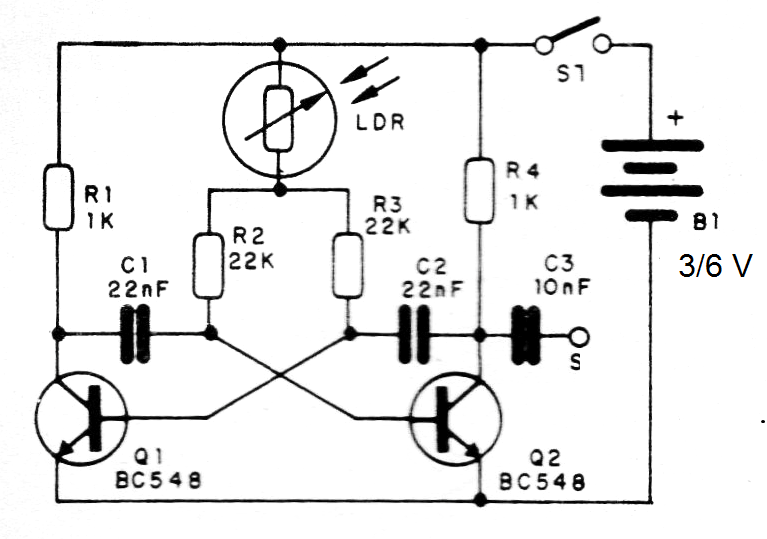
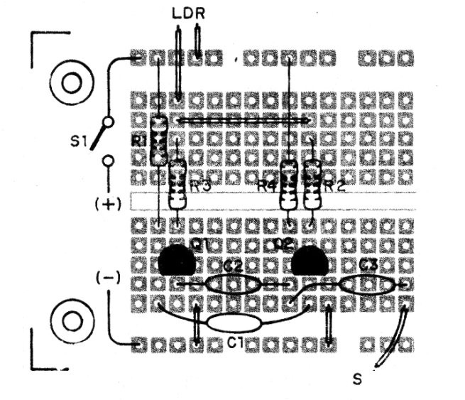
The capacitors C1 and C2 can have their values changed, as they determine the frequency. Values between 10 and 470 nF can be experienced. The resistors are 1/8 W and the LDR can be of any type.
The output can be connected to a ceramic capsule or to the input of a small amplifier. It can also be connected to a frequency meter. For the component values given in the circuit the frequency is around 1 kHz.
Material list
Q1, Q2 - BC548 - general purpose NPN transistors
Common LDR-LDR
B1- 3 V or 6 V - 2 or 4 small batteries
S1 - Single Interrupter
C1, C2 - 22 nF - ceramic or polyester capacitors - see text
R1, R4 - 1k ohm x 1/8 W - resistors - brown, black, red
R2, R3 - 22k x 1/8 W- resistors - red, red, orange
Miscellaneous: protoboard, battery holder, wires, solder, etc.


