
The circuit presented has an extremely low current draw, thus preventing batteries or batteries used in the power supply from draining quickly. The unit can be turned on for months without this happening. In figure 1 we have the complete diagram of this low consumption alarm.
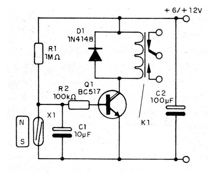
Note that the sensor is a reed-switch that should remain closed with the proximity of a magnet. Under these conditions the current in the circuit is given by R1 and by the supply voltage. When the magnet moves away from X1 the capacitor C1 charges to the point where Q1 conducts and drives the relay.
This means that as a function of C1 we can have trigger delays ranging from a few seconds to a few minutes. Values between 100 nF and 100 uF can be experienced. In figure 2 we have a suggestion of printed circuit board for this assembly.
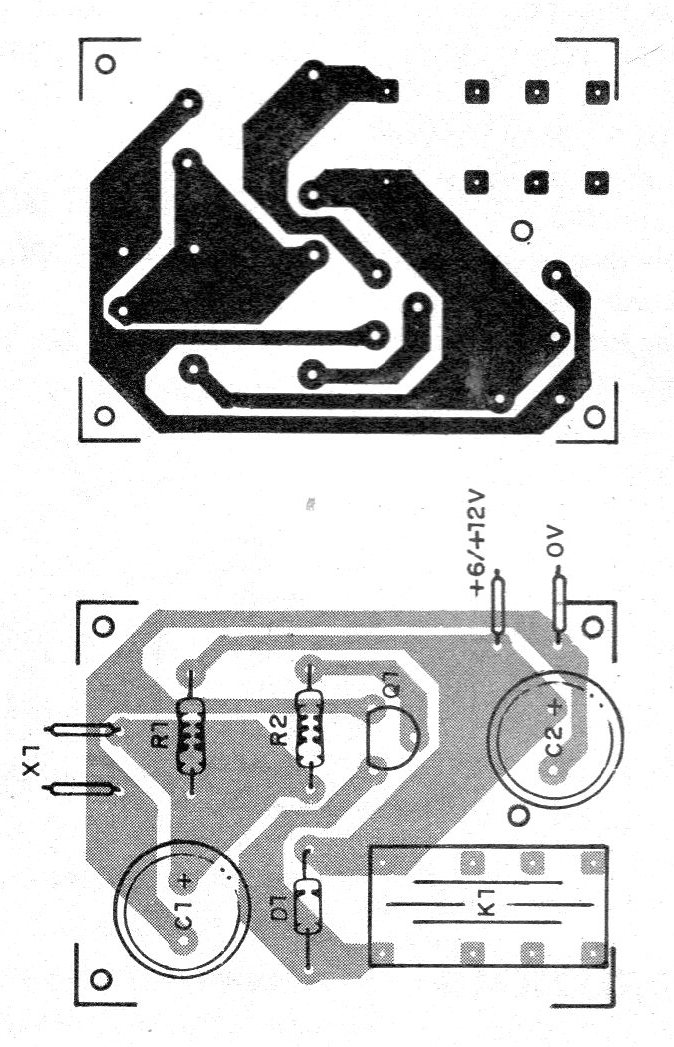
The relay depends on the supply voltage and can be replaced by equivalents with corresponding change in the arrangement of the terminals on the board.
If more than one sensor is used; can be connected in series. The quantity is limited and its connection can also be made with long wires.
Material list
Q1 - BC517 - Darlington transistor
D1 - 1N4148 - general purpose diode
X1 - Sensor - see text
R1 - 1 M ohm - resistor - brown, black, green
R2 - 100k ohm - resistor - brown, black, yellow
C1 - 10 uF - electrolytic capacitor
C2 - 100 uF - electrolytic capacitor
K1 - 6 or 12 V relay
Several: Printed circuit board, wires, solder, etc.


