
High frequency circuits, such as those operating with FM signals, are critical and should not be mounted on contact dies or terminal bridges. However, if we are careful, we can have reasonable results, which is interesting in a didactic project, such as the one we present.
In high frequency circuits the wires and component terminals must be kept as short as possible.
This limits its use to printed circuit boards and even so, with care in the lengths of the tracks.
However, for didactic purposes it is possible to mount a simple tuner that can pick up nearby stations using a terminal bridge.
It is clear that the wires should be kept short and a certain instability of operation can occur with the approach of objects or even the hand of the operator.
The circuit signal shown must be applied to the input of an amplifier, and we can change its coil so that it also picks up the signals from the VHF band.
Thus for the FM range the coil consists of 4 turns of hard wire with a diameter d 1 cm without core and for VHF we can try 2 or 3 turns of the same wire with the same diameter.
The antenna may be of the telescopic type or a piece of wire 30 to 60 cm long in the upright position.
In figure 1 we have the complete tuner diagram.
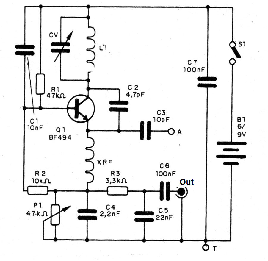
In figure 2 we have the arrangement of the components in the terminal strip.
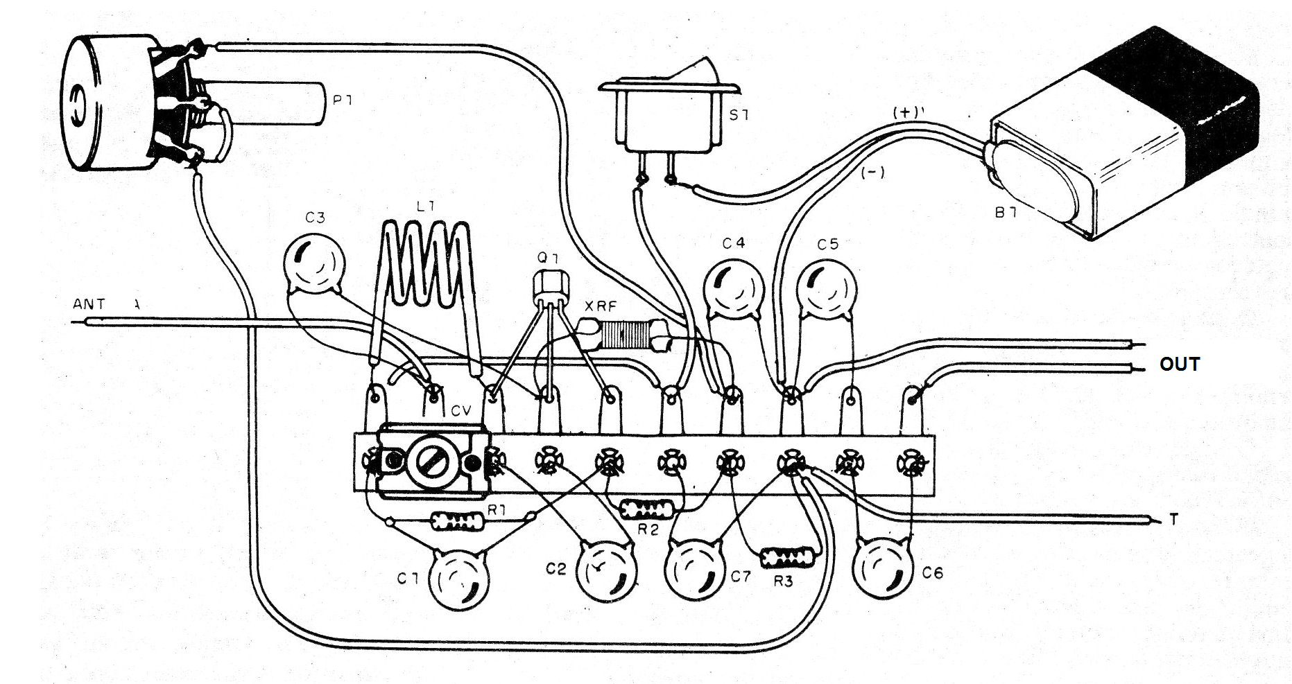
The variable capacitor is harnessed from an FM radio, but the tuning can also be done by a trimmer.
Be careful not to use the AM section of the variable capacitor because with it the circuit will not work.
The RF shock can be a microfuge of 47 uF or even manufactured by winding about 30 or 40 turns of fine wire on a 1M ohms x ¼ W resistor and connecting the wires to the resistor terminals.
The power can be made with 4 small batteries or a 9 V battery.
The capacitors must all be ceramic and the audio cable for the input of the amplifier must be shielded.
To use, set P1 to get the best throughput while tuning the capacitor to pick up some station.
With 5 or 6 turns the sounds of the low TV channels (2 to 5) can be picked up.
Material list
Q1 - BF494 - RF transistor
L1 - Coil - see text
XRF - microchoke - see text
CV - variable capacitor - see text
B1 - 6 or 9 V - 4 batteries or battery
A - antenna - see text
S1 - Single switch
P1 - 47 k - trimpot
R1 - 47 k ohms x 1/8 W - resistor - yellow, violet, orange
R2 - 10 k ohms x 1/8 W - resistor - brown, black, orange
R3 -3k3 x 1/8 W - resistor - orange, orange, red
C1 - 10 nF - ceramic capacitor
C2 - 47 pF - ceramic capacitor
C3 - 10 pF - ceramic capacitor
C4 - 2.2 nF - ceramic capacitor
C5 - 22 nF - ceramic capacitor
C6 - 100 nF - ceramic capacitor
Several:
Battery connector or battery holder, terminal strip, wires, soles, etc.


