
Small inverters can help you get high voltages from batteries or batteries. Although keyed inverters that are integrated elevator sources are much more efficient in converting power and therefore preferred in modern applications, traditional analogue versions can still be used to solve immediate practical problems or do not require high efficiency.
One application case is the replacement of 22.5 V batteries used in some types of multimeters and other older lab instruments that, in addition to being expensive, are difficult to find. Recently we even received requests from readers to publish this type of source.
Another application is in the feeding of Geiger tubes and some other types of transducers that need high voltages under low current regime.
In figure 1 we have the diagram of our power supply
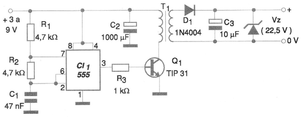
The transformer will determine the voltage obtained in the secondary, and can be rolled experimentally with the use of a ferrite core. This core can be harnessed from an old switched computer source that no longer works.
Then wrap the primer with 60 turns of 28 AWG enameled wire and then using 32 AWG wire wind up the number of turns necessary to obtain the voltage you want. For example, if you want something around 22.5 V from 4 cells (6 V) wind 22/6 x 60 = 220 turns.
It should be noted that the waveform generated by the circuit is not perfectly sinusoidal, which means that the secondary can have peaks much larger than 22.5 V. The reader can experiment with other winding ratios so as to obtain the best yield for its source.
In order to obtain very high voltages a horizontal output transformer (fly back) of TV or video monitor may be used, which in some cases already contains a tripler. A type having the exposed core is to be sought so that it is possible to wind the primary winding.
Thus, after rectification it is necessary to filter and regulate this voltage with a zener or an IC. In our example, for 22.5 V, we use a zener of 1 W.
In figure 2 we have a suggestion of printed circuit board for the assembly of this high voltage source.
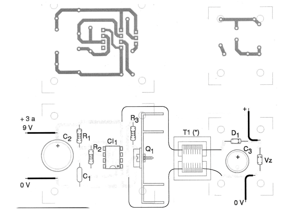
The resistors R1 and R2 as well as C1 can have their values changed experimentally in order to obtain the best performance of the circuit. The power transistor shall be provided with a heat radiator.
Material list
CI-1 - 555 - integrated circuit
Q1 - BD135 or TIP31 - medium power NPN transistor
Z1 - Zener according to the output voltage
D1 - 1N4004 - rectifier diode
T1 - Power Transformer - see text
R1, R2 - 4.7 k ohm x 1/8 W - resistor
R3 - 1 k ohm x 1/8 W - resistor
C1 - 47 nF - polyester capacitor
C2 - 1000 uF x 12 V - electrolytic capacitor
C3 - 10 uF - electrolytic capacitor
Several:
Printed circuit board, heat radiator for the transistor box for mounting, wires, solder, etc.


