This simple oscillator emits a signal that produces, in analog televisions (vHF and UHF range), a standard of horizontal bars. The standard can be used to adjust linearity and the device itself to test the directivity and efficiency of an antenna system.
The circuit shown in figure 1 is very simple, employing only three transistors.
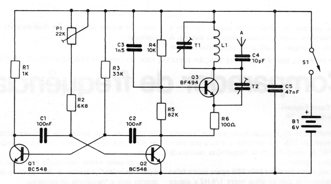
Transistors Q1 and Q2 form a multivibrator that produces the low frequency that will be responsible for the bars (modulation), the width of the bars as well as their separation are controlled by the frequency of this multivibrator that can be set at P1.
The capacitors C1 and C2 that fix the average value of the separation and width of the bars can be modified if the reader chooses. The third transistor functions as an RF oscillator that has its frequency determined by L1 and trimmer setting.
The used trimmer has been removed from an old radio but in principle any trimmer can be used. The coil L1, with 4 turns of wire 20 in diameter of 1 cm, without core, allows to take the apparatus to produce its signals in channel 2 or 3.
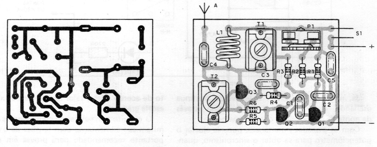
The antenna consists of a piece of wire from 10 to 15cm and the power is made by 4 batteries or 9V battery. In figure 2 we have a suggestion for printed circuit board.