
We present a simple test of NPN and PNP transistors that, besides saying if the component is good, indicates with good precision its gain. Of great use to all who perform electronic assemblies, this test is totally portable and works on batteries.
Simply connect the transistor to be tested to the corresponding terminals and then turn potentiometer P1 until one of the indicator LEDs comes on. The point at which this occurs determines the gain of the transistor. If the LED lights up at the end of the P1 cursor, or does not light, the transistor is experiencing problems.
The circuit is powered from a 6V source and transistors of all types can be tested, with gains in the range of 0 to 1000. If you do not yet have an instrument for testing your transistors, you should not miss this one.
HOW IT WORKS
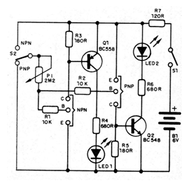
Taking as reference the NPN transistor test sector, which is constituted by transistor Q1 and its polarization components, we have the following operation: in the absence of a transistor in test, the resistor R3, between the emitter and the base of Q1, polarizes the latter in its region of cut, preventing the driving, so that we have no current collector. The LED remains off. With the connection of an NPN transistor its collector current must polarize the transistor QI to the point where it starts conducting and consequently lights the LED1.
This is in function of the base current of the transistor in test, which is determined by P1. Thus, by turning P1 from the point of greatest resistance, we arrive at a point where the polarization of its base is sufficient to have a collector current that leads Q1 to conduction, lighting the LED.
By varying the base current of the transistor in test, through P1, we will be varying the collector current. Since the ratio of collector current to base current is the transistor gain itself, the variation of P1 will be proportional to the gain of the component under test. Gains greater than 1000 can be achieved with a potentiometer of 2M2 or even 4M7. .
The PNP transistor testing sector works the same way, with the difference that we have opposite directions of current flow.
ASSEMBLY
In figure 1 we have the complete circuit of the tester.
The assembly carried out on a terminal strip is shown in figure 2.
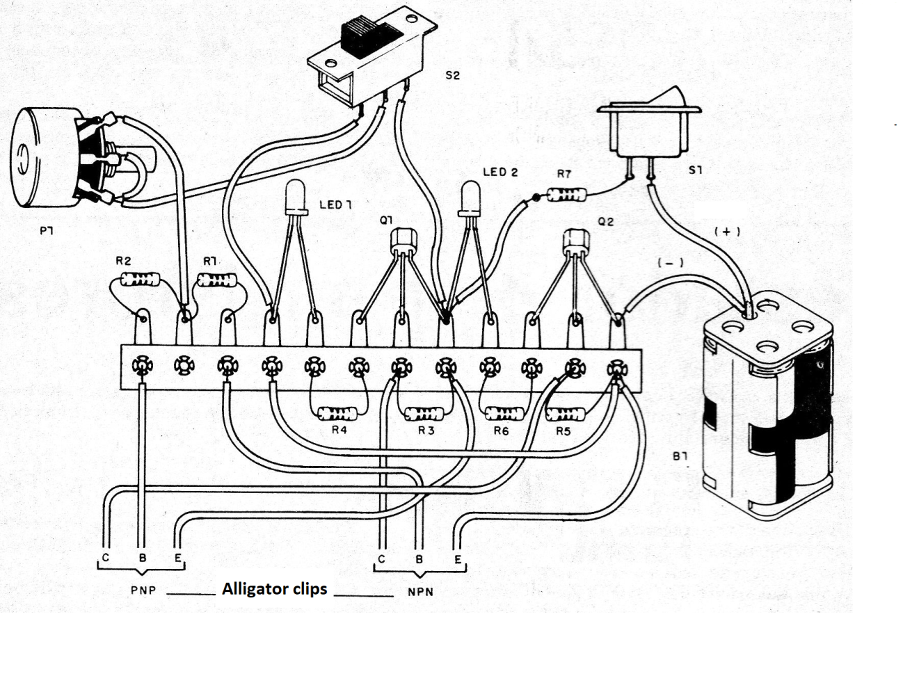
The resistors are all 1/8 or ¼ W and the potentiometer P1 can be linear of 2M2, in which case the scale suggested in figure 3 fits well. LEDs are common and may be of different colors.
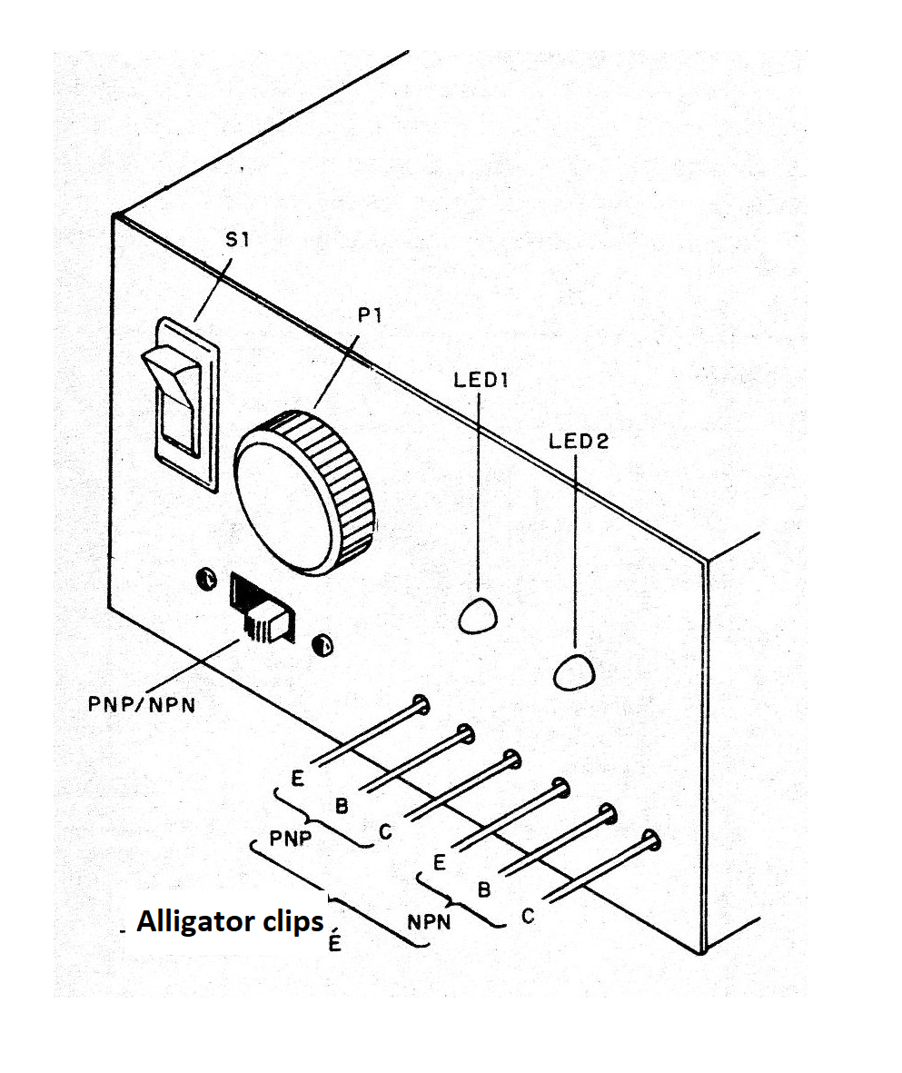
For the power supply, 4 small batteries are used.
TEST AND USE
To test, connect a transistor to the approving claws according to their polarity (NPN or PNP) and then slowly rotate P1 until the corresponding LED lights up. At this point we have the transistor gain indication. If the LED lights up in the entire course of P1, it signals that the transistor is short, and if it does not light the transistor is signaled.
MATERIAL LIST
Q1 - BC548 or equivalent - general purpose NPN transistor
Q2 - BC558 or equivalent - general purpose PNP transistor
LED1 - Common red LED
LED2 - red or green common LED
B1 - 6 V - 4 small batteries
S1 – On/Off switch
S2 - 1-pole wrench x 2 positions (or H)
P1 - 2M2 - linear potentiometer
R1, R2 - 10k - resistors (brown, black, orange)
R3, R5 -180 ohm - resistors (brown, gray, brown)
R4, R6 - 680 ohm - resistors (blue, gray, brown)
R7 - 120 ohm - resistor (brown, red, brown)
Miscellaneous: 4 small cells holder, mounting box, terminal strip, knob for potentiometer, scale for potentiometer, alligator clips of different colors (6) for connection of transistor in test, wires, welding etc.


