
This small timer can be used with the most diverse purposes such as timing the cooking time of an egg, corrosion of a plate, a play in a chess match the response in a competition. Times from a few seconds to more than 15 minutes can be obtained.
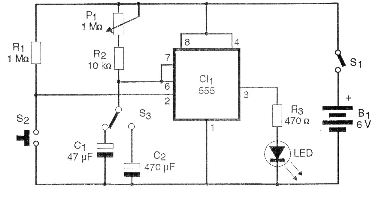
This simple timer causes an LED to remain lit for the time set in the potentiometer.
With C1 of 47 uF we obtain times of up to a few minutes and with C2 of 470 uF this time extends to more than 15 minutes.
Using a capacitor of 1 000 uF or 1 500 uF we can get to near an hour.
Based on a stopwatch or a clock, we can calibrate the time scale of P1.
In figure 1 we have the complete diagram of the timer.
The assembly on a printed circuit board can be made as shown in figure 2.
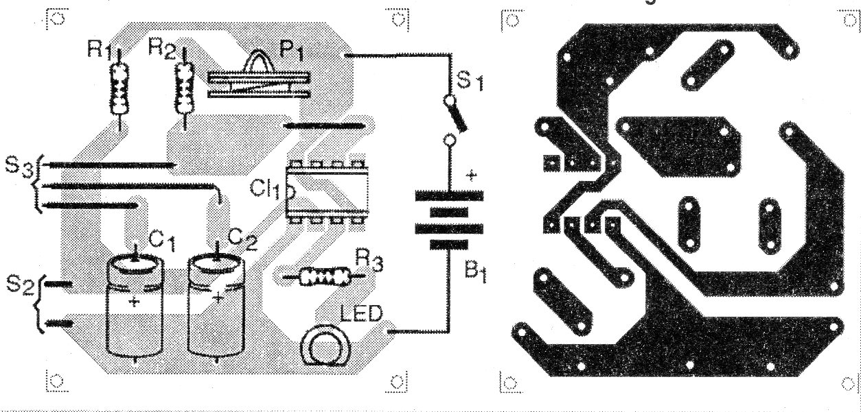
On assembly, observe the position of the integrated circuit and the polarity of the LED as well as the power supply.
The resistors are 1/8 W with any tolerance and the electrolytic capacitors for 6 V or more working voltage.
The LED can be of any color and the power is supplied with 4 small batteries (AA) or toothpick (AAA).
By increasing R3 to 1 k, the circuit can be powered by a 9 V battery.
The LED is of any color and the potentiometer is of any type.
Material list
CI-1 - 555 - integrated circuit
LED - common LED of any color
S1 – On-Off switch
S2 – Push-button NA
B1 - 6 V - 4 AA or AAA batteries
P1 - 1 M ohms - potentiometer
R1 - 1 M ohms - resistor - brown, black, green
R2 - 10 k ohms - resistor - brown, black, orange
R3 - 470 ohms - resistor - yellow, violet, brown
C1 - 47 uF - electrolytic capacitor
C2 - 470 uF or 1 000 uF - electrolytic capacitor
Several:
Printed circuit board, battery holder, mounting box, potentiometer knob, wires, solder, etc.


