
The circuit of figure 1 causes an incandescent lamp to flash at a rate determined by the setting of P1.
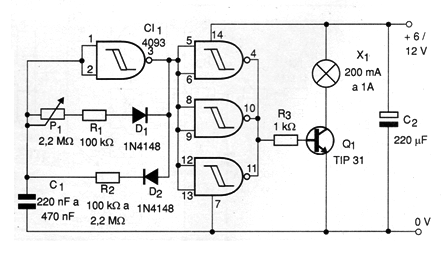
The active cycle, or time that the blink lasts, is determined by the resistor R2. For very short flashes, the resistor can have values between 10 k ohms and 100 k ohms. For longer flashes its value will be between 220 k ohms and 2.2 M ohms.
The blinking frequency is set to P1.
The power transistor depends on the lamp used. For lamps up to 1 A we recommend using a TIP 31 mounted on a good heat radiator.
In figure 2 we give a printed circuit board suggestion to implement this flag.
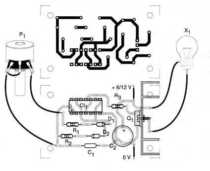
An interesting application is in automotive signaling systems, where several 200 mA lamps can be connected in parallel.
Material list
CI-1 - 4093 - CMOS integrated circuit
Q1 - TIP31 - NPN power transistor
D1, D2-1N4148 or equivalent - general purpose diodes
R1 - 100 k ohms x 1/8 W - resistor - brown, black, yellow
R2 - 100 k ohms at 2.2 M ohms x 1/8 W - resistor - see text - determines the active cycle
R3 - 1k ohms x 1/8 W - resistor - brown, black, red
P1 - 2.2 M ohms - potentiometer
C1 - 220 nF to 470 nF - ceramic or polyester capacitor
C2 - 220 uF x 16 V - electrolytic capacitor
X1 - 6 or 12 V up to 1 A - incandescent lamp
Several:
Printed circuit board, heat radiator for transistor, mounting box, wires, solder, etc.


