
The circuit of figure 1 causes two lamps to flash alternately at a frequency that can be set at P1.
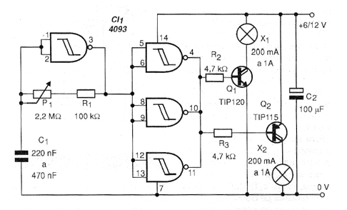
One of the NAND gates is used as an oscillator, whose frequency depends basically on the value of C1, whereas the other gates are configured as digital amplifiers and connected in parallel to be able to excite two complementary transistors.
For small bulbs up to 50 mA low-power transistors such as the BC548 / 558 can be used. For higher current lamps the TIP120 and TIP115, mounted on heat radiators, should be used.
The supply voltage of the circuit depends on the used lamp.
One of the possible applications for this circuit is in emergency signaling, in automotive use triangles or even in vehicle exit signaling. A power source according to the current and voltage of the lamps must be used.
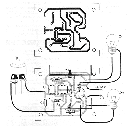
In figure 2 we have a suggestion of printed circuit board for the assembly of the version with power transistors.
Material list
Semiconductors:
CI-1 - 4093 - CMOS integrated circuit
Q1 - TIP120 - Power Darlington NPN Transistor
Q2 - TIP115 - PNP Darlington power transistor
Resistors: (1/8 W, 5%)
R1 - 100 k ohms - brown, black, yellow
R2, R3 - 4.7 k ohms - yellow, violet, red
P1 - 2.2 M ohms - trimpot
Capacitors:
C1 - 220 nF to 470 nF - ceramic or polyester
C2 - 100 uF x 16 V - electrolytic
Several:
Printed circuit board, heat radiators for the transistor, power supply according to the power and voltage of the lamps, wires, solder, etc.


