
This short-range didactic project sends signals to a nearby radio tuned in both the medium and short wave range, depending only on the coil. This is a good suggestion for school work or even telecom or electronic work of the early years (STEM).
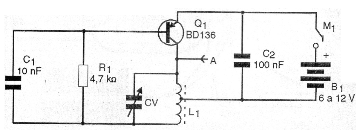
The circuit presented consists of a simple Hartley oscillator with a transistor and a small antenna transmits its signals to receivers up to a few tens of meters.
The transmission is CW or continuous wave, used in telegraphy, serving for demonstrations of how this mode of communication works.
See more in Telegraphy (ALM253) and Morse Code (ALM246) for complete information on this mode of communication.
The circuit is powered by common batteries and all components are inexpensive.
In figure 1 we have the complete diagram of the transmitter.
In figure 2 we have the terminal strip mounting, although the circuit can also be mounted in a protboard.
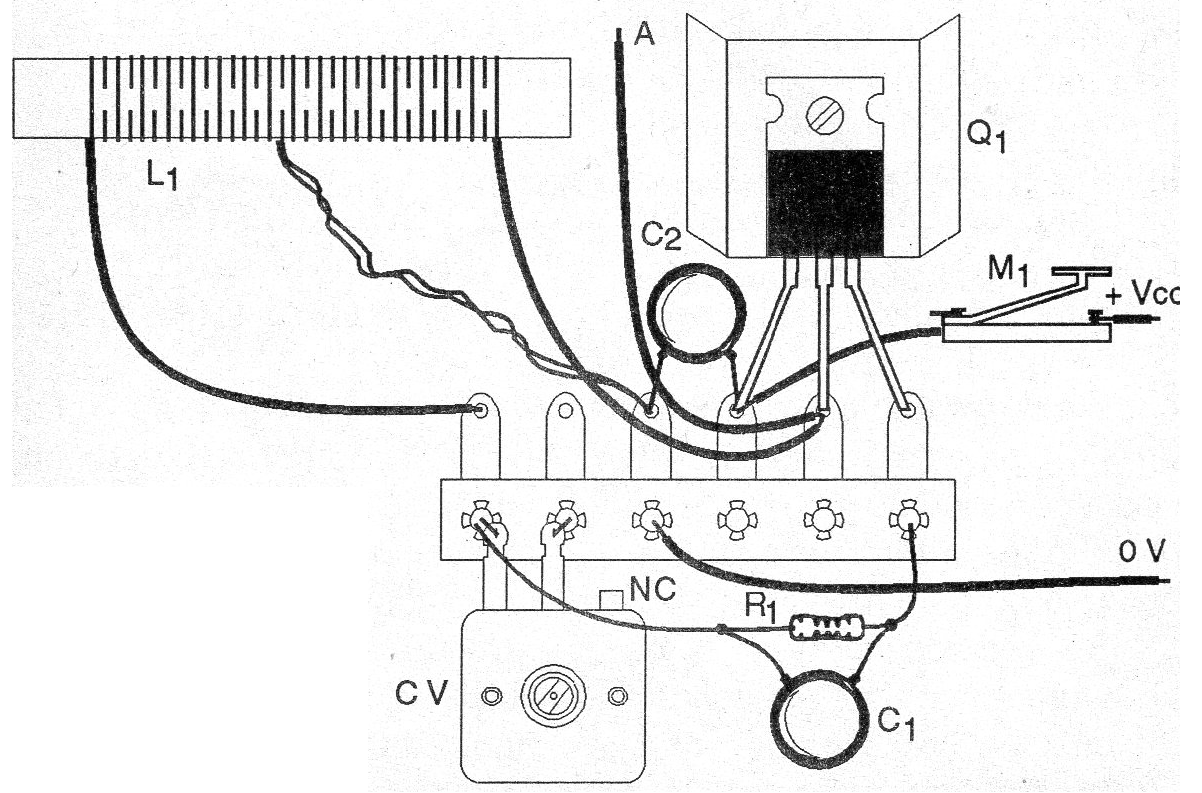
For the medium-waveband L1 consists of 80 turns of wire 28 or even rigid telephone wire in a ferrite stick, with central socket.
To operate in the shortwave range between 5 and 15 MHz wind 20 + 20 or 15 + 15 turns of the same wire on the same pole.
The capacitors are ceramic and the variable capacitor is taken advantage of an old AM radio out of use.
For 12 V power supply, the transistor must be equipped with a small heat sink.
If source is used, it must have at least 600 mA of current capacity.
The morse key can be improvised, or built according to many designs we describe on this site.
The antenna can be a wire stretched from 1 to 5 meters in length.
Material list
Q1 - BD136 - PNP power transistor
L1 - Coil - see text
CV - variable capacitor - see text
C1 - 10 nF - ceramic capacitor
C2 - 100 nF - ceramic capacitor
B1 - 6 or 12 V - batteries or source - see text
M1 – Morse key - see text
R1 - 4k7 ohms x 1/8 W - resistor - yellow, violet, red
Several:
Terminal strip or contact array, ferrite rod, battery holder or source, wires, solder, etc.


