
This simple circuit can be used in science fairs, demonstrations or classes to show the principle of operation of a vibrator, as curiosity or in a call or alarm system.
It is a circuit that excites a vibrator built with pieces of scrap and produces a sound that depends on the setting of P1. The intensity of the sound will depend on the way you mount your vibrator.
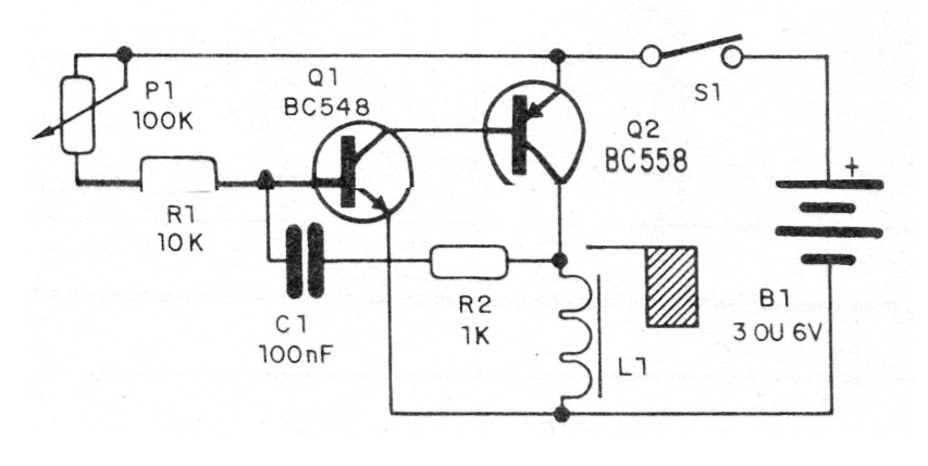
What we have is an oscillator whose frequency depends on capacitor C1 and also on the setting of P1. The power can be made with voltages of 3 to 6 V obtained from common batteries. In figure 1 we have the complete diagram of the apparatus.
The assembly can be made by soldering the main components in a terminal strip, as shown in figure 2.
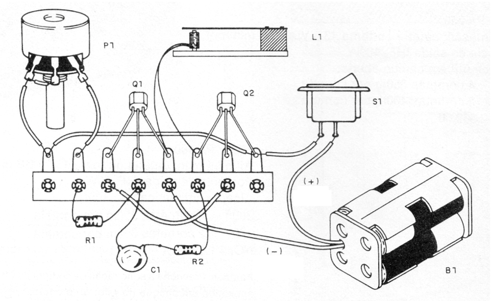
We suggest experimenting with capacitors in the range of 22 nF to 470 nF, according to the vibrator. In figure 3 we have details of the construction of the vibrator.
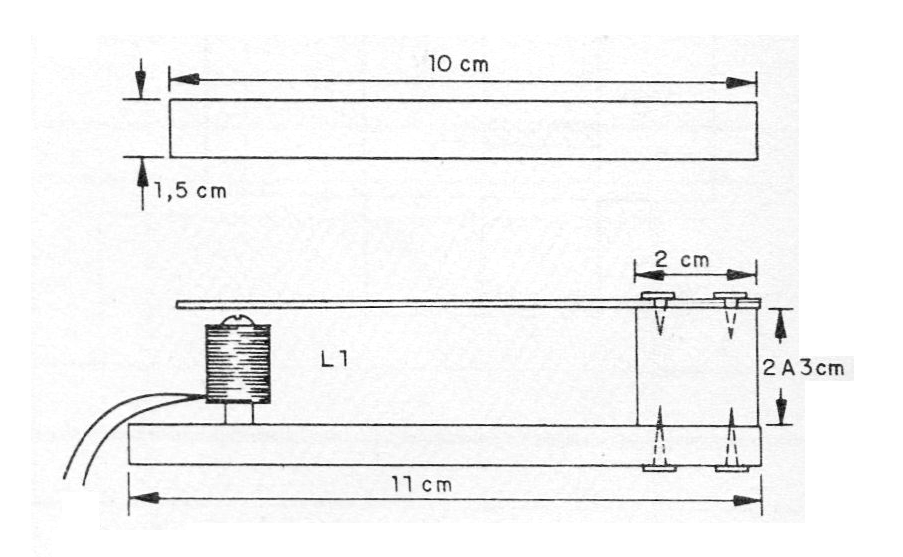
The coil L1 is formed by 200 to 400 turns of fine enameled wire, for example the 32 AWG that can be obtained from the winding of a faulty transformer. Note that the transformer can not be burned, but with another defect, since the burned wire is no longer insulated.
The metal part of the vibrator can be made with cut cans (be careful not to get hurt) attached to a piece of wood and a stump.
To test the unit, simply turn it on and set P1 to have the best sound output. The circuit can be powered with voltages up to 12 V by replacing Q2 with a BD136 with a heat radiator.
Material list
Q1- BC548 - general purpose NPN transistor
Q2 - BC558 - general purpose PNP transistor
L1- vibrator - see text
S1- Push button
B1 - 3 to 6 V - two to four small batteries
P1- 100k ohm - potentiometer
R1- 10k ohm x 1/8 - resistor - brown, black, orange
R2- 1k ohm x 1/8 W - resistor - brown, black, red
C1- 100 nF - capacitor - see text
Miscellaneous: support of batteries, terminal strip, pieces of wood and tin for the construction of the vibrator, wires, weld, etc.


