
We have shown in this article a transistorized version of AM radio for local stations that works with voltages between 1.2 and 1.8 V. One possible use for this radio is in emergency situations when there is no other form of energy available besides solar , or in demonstrations. It is clear that the experimental application should not be omitted since it is a very simple circuit.
Note: The 1988 article uses a solar cell available at the time. However, any 2 to 9 V cell will work with this circuit.
To gather good sensitivity, listen in loudspeaker and power with low voltage (between 1.2 and 1.8 V), we made an amplifier circuit with 3 high-gain transistors. This circuit, although simple, captures the strongest stations even without antenna and provides reasonable listening on a small speaker and, better yet, on a low-impedance headset.
High impedance earphone can also be used by simply having the T1 transformer removed. As it is a direct amplification receiver, to simplify the project to the maximum, we do not have excellent selectivity, but listening to local stations is good.
An important feature of the design, however, is that its current consumption is low (on the order of 5 mA), which means that solar cells can be used even with relatively low illumination such as a regular bulb or even a lamp.
HOW IT WORKS
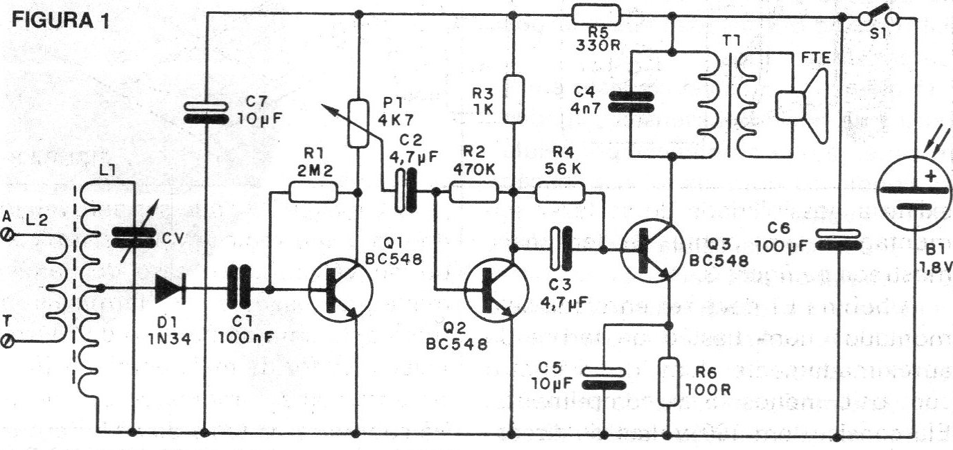
The coil L2 together with CV tunes the signal of the station to be heard. By changing the number of turns (reduction) we can eventually pick up stronger stations in the shortwave band. The detection is done by the D1 diode, which must be Germanium, and the audio signal is taken to the first amplifier transistor, which is Q1.
In order to avoid possible circuit oscillations, a capacitor of 470 pF may be connected between the base and the emitter of Q1. From the Q1 collector is drawn the signal for the next step via P1, a potentiometer of 4k7 that will act as volume control.
We then have successive amplifications made by Q2 and Q3 until the signal acquires sufficient intensity to be brought to a loudspeaker. As the output impedance of Q3 is relatively high compared to that of the speaker we use a miniature output transformer to make the match (T1).
This transformer can be obtained from out-of-use transistor radios. If you can choose one, among several, that presents the best performance, thus ideally matching the characteristics of the circuit with that of the speaker used.
For best sound quality it is recommended to use a speaker of at least 10 cm in diameter mounted on a small speaker. The capacitor C6 acts as a "reservoir" eliminating the influences in the circuit of light variations (especially in the case of a lantern flame).
ASSEMBLY
The complete circuit of the radio is shown in figure 1.
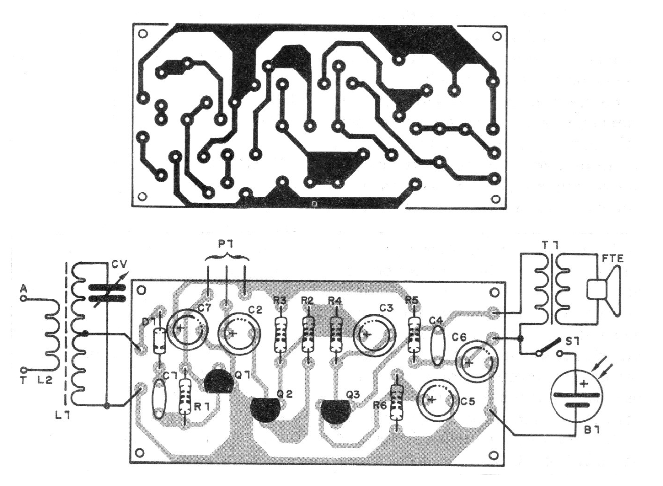
In figure 2 we have a printed circuit board suggestion for this project.
The radio can be installed in a small wooden box (never metal) with the cell attached to its cover. As it is a didactic project there is the possibility of making its bridge assembly of terminals, shown in figure 3.
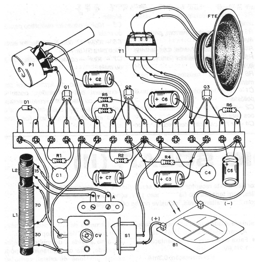
The coil L1 must be coiled by the assembler on a ferrite rod of approximately 1 cm in diameter at least 15 in length. It consists of 100 turns of enameled wire 28 or close to it with socket on the 30th turn from the negative bond side. L2 consists of 15 turns of the same wire next to L1, as shown in figure 3.
If it is difficult to obtain enameled wire, even ordinary wire serves, provided that it is not too thick to the point where the whole set of turns does not fit on the ferrite rod. For this case, L2 can be wrapped around L1.
The connection to the antenna and earth can be made by a pair of terminals or terminals. For the transistors, equivalents such as BC237, BC238, BC239, BC547 or BC549 are allowed. For D1, any germanium diode can be used.
The electrolytic capacitors are for 3 V or more and the resistors all of 1/8 or 1 / 4W. The smaller capacitors (C1 and C4) are ceramic or polyester. The variable CV can be found in an old transistorized AM or tube radio. In the case of the miniature variable we use the middle terminals and one end (type of 3 terminals), and if it is from more terminals we try the combination or pair that covers the AM band.
For large variables, from tube radios, the connection is made to the set of fixed plates and the movable assembly of one of the sections. Before taking advantage of the variable, make sure that the fixed plate assembly does not touch the movable plates when moving the shaft.
TEST AND USE
For the connection of the solar cell it is necessary to observe its polarity. Connect an antenna of at least 3 meters at point (A) and the point (T) to ground which may be neutral pole of the outlet or any metal object in contact with the ground.
Even holding the wire (T) between your fingers already means a "reasonable" land. Light the solar cell and try to tune to the desired stations. If instability occurs, connect a capacitor of 470 nF between the base and the emitter of Q1.
Material list
Q1, Q2, Q3 - BC548 or equivalent - general purpose NPN transistors
D1 - 1N34 or equivalent - germanium diode
P1 - 4k7 - potentiometer
T1 - output transformer with 200 to 1000 ohm primary
B1 - solar cell - see text
S1 – On-Off switch
L1, L2 - Coils (see text)
CV - variable (see text)
FTE - 8 ohm x 10 cm speaker
R1 - 2M2 - resistor (red, red, green)
R2 - 470 k - resistor (yellow, violet, yellow)
R3 - 1k - resistor (brown, black, red)
R4 - 56k - resistor (green, blue, orange)
R5 - 330 ohm - resistor (orange, orange, brown)
R6 - 100 ohm - resistor (brown, black, brown)
C1 - 100 nF - ceramic or polyester capacitor
C2 - C3 - 4.7, uF - electrolytic capacitors for 3V or more
C4 - 4n7 - ceramic or polyester capacitor
C5 - 10 uF - electrolytic capacitor for 3 V or more
C6 - 100 uF to 1000 uF - electrolytic capacitor for 3 V or more
C7 - 10 uF - electrolytic capacitor for 3 V or more
Miscellaneous: ferrite wand, mounting box, enameled wires, terminal bridge or printed circuit board, loudspeaker speaker, low impedance (optional) handset, wires, solder, etc.


