
If you have an unregulated power supply and want to regulate currents up to 1 A economically, this circuit can be used. Newton C. Braga
Read more:
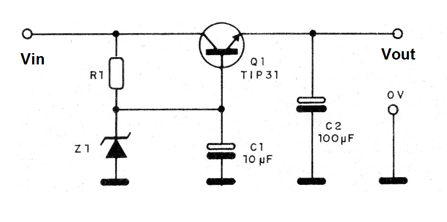
We describe the assembly of a single voltage regulator for currents up to 1 A using a transistor and a zener diode as the main components.
The output voltage depends on the zener, which can be from 6V6 to 12V for voltages from 6 to 12 V.
The input voltage must be at least 2 V more than the output voltage, but less than 20 V in all cases.
The power transistor must be mounted on a heat radiator.
The electrolytes are for 12 V or more and R1 depends on the voltage of the voltage difference between input and output, according to the following table:
2 to 6 V - 330 ohms
6 to 9 V - 470 ohms
9 to 12 V - 680 ohms
In figure 1 we have the regulator diagram.
In figure 2 we have its assembly on a terminal strip.
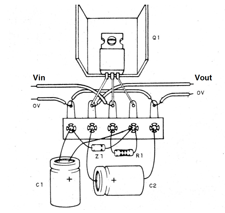
On assembly, note the position of the integrated circuit and polarity of the zener diode and electrolytic capacitors.
Material list
CI-1 - 7806 - integrated circuit
Z1 - Zener according to output voltage - see text
R1 - see text
C1 - 10 uF - electrolytic capacitor
C2 - 100 uF - electrolytic capacitor
Several:
Terminal strip, mounting box, heatsink, wires, solder.


