
If you need a circuit to produce a continuous tone in a ceramic buzzer or piezoelectric capsule, here's a simple setup using ordinary transistors.
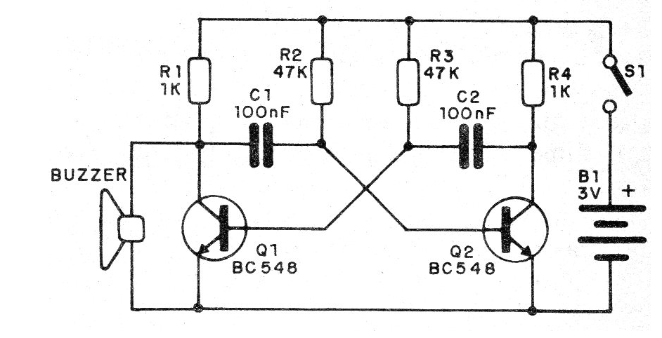
The circuit shown is an astable multivibrator that can be powered with voltages from 3 to 12 V and in some cases can even operate with 1.5 V.
The frequency depends on the capacitors, which can be altered in order to obtain the desired sound, or to obtain the resonant frequency of the transducer, in which case we obtain higher efficiency.
The complete circuit of the buzzer is shown in figure 1.
The assembly can be done either in a protoboard or in a terminal strip.
For the terminal strip we have the arrangement of the components in figure 2.
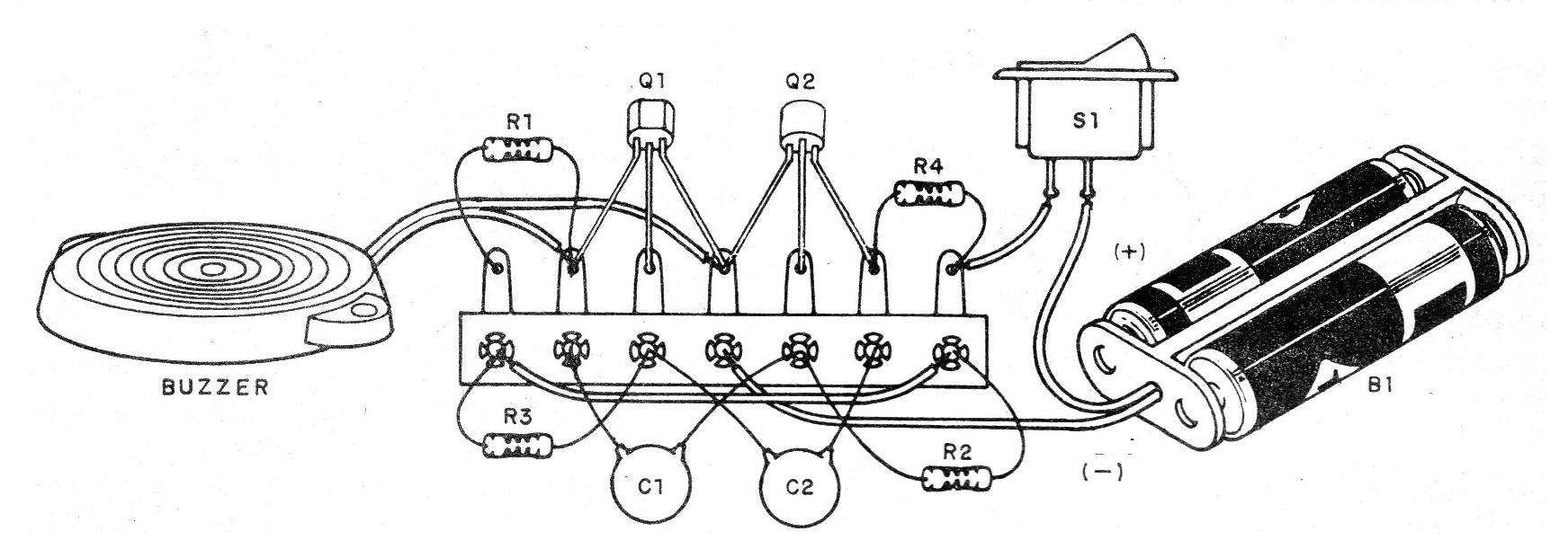
Observe the positions of the transistors in the assembly.
The resistors are 1/8 W with any tolerance and the capacitors can be ceramic or polyester.
For power above 9 V, increase R1 and R4 to 2k2 ohms.
Material list
Q1, Q2 - BC548 - general purpose NPN transistors
C1, C2-10 nF at 100 nF - capacitors
R1, R4 - 1k ohms - resistors - brown, black, red
R2, R3 - 47 k ohms - resistors - yellow, violet, orange
B1 - 3 to 12 V - batteries or battery
S1 – On-Off switch
Several?
Battery holder, terminal bridge, wires, solder.


