
Piezoelectric buzzers have a higher yield with higher voltage signals. The circuit shown may serve as a metronome, a gymnastic rhythm marker, and is based on a single-acting transistor by exciting a buzzer through a small transformer.
The frequency of the pulses can be adjusted over a wide range of values through a potentiometer or trimpot and the power can be made with voltages between 6 and 12 V. In figure 1 we have the complete diagram of the oscillator.
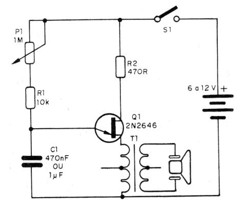
The capacitor C1 is charged through R1 and R1 to the trip point of the unijunction. The discharge occurs through the transformer. In Figure 2 we have the arrangement of the components on a terminal strip.
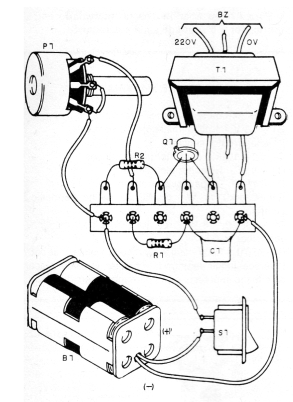
The transformer is a primary power supply type of 110 V or 220 V and a secondary voltage of 5 to 9 V with a current between 50 and 300 mA. A small transformer output transformer can also be used. The low voltage winding is connected to the transistor.
The buzzer is ceramic type and the capacitor can be of any type. For a 4-cell battery use the appropriate battery holder. On assembly, observe the correct positions of the components.
Material list
Q1 - 2N2646 - Single-pole transistor
T1 - Transformer - see text
BZ- Buzzer or piezoelectric transducer
S1 – On-Off Switch
B1 - 6 to 12 V - batteries, battery or power supply
P1 - 1 M ohm- potentiometer
R1 - 10 k ohm x 1/8 W - resistor - brown, black, orange
R2 - 470 ohm x 1/8 W - resistor - yellow, violet, brown
C1 - 470 nF at 1 uF - polyester or electrolytic capacitor
Miscellaneous: terminal strip, battery holder, wires, solder, etc.


