
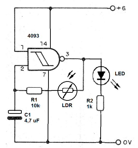
By mounting this circuit in an array of 170 points we can learn how an oscillator configuration with the 4093 integrated circuit can have its frequency controlled by an LDR.
As we know, the frequency of the oscillator with the 4093 is determined by both the capacitor and the resistor. They form a time-wave circuit. The time constant RC determines the time it oscillates, ie T = R x C.
If we connect in series with the resistor an LDR, the resistance of the LDR sums up the resistance of this component, and as it depends on the light, the time constant changes with the light. Thus, in the dark, the LDR has a higher resistance and thus increases the time constant with decreasing blink frequency.
In the light we have lower resistance of the LDR and with that the circuit oscillates faster.
Assembly
In figure 1 we have the complete circuit of the flasher that drives an LED using the integrated circuit 4093 and having its frequency controlled by the light incident on the LDR.
The circuit assembly in the protboard shown in figure 2.
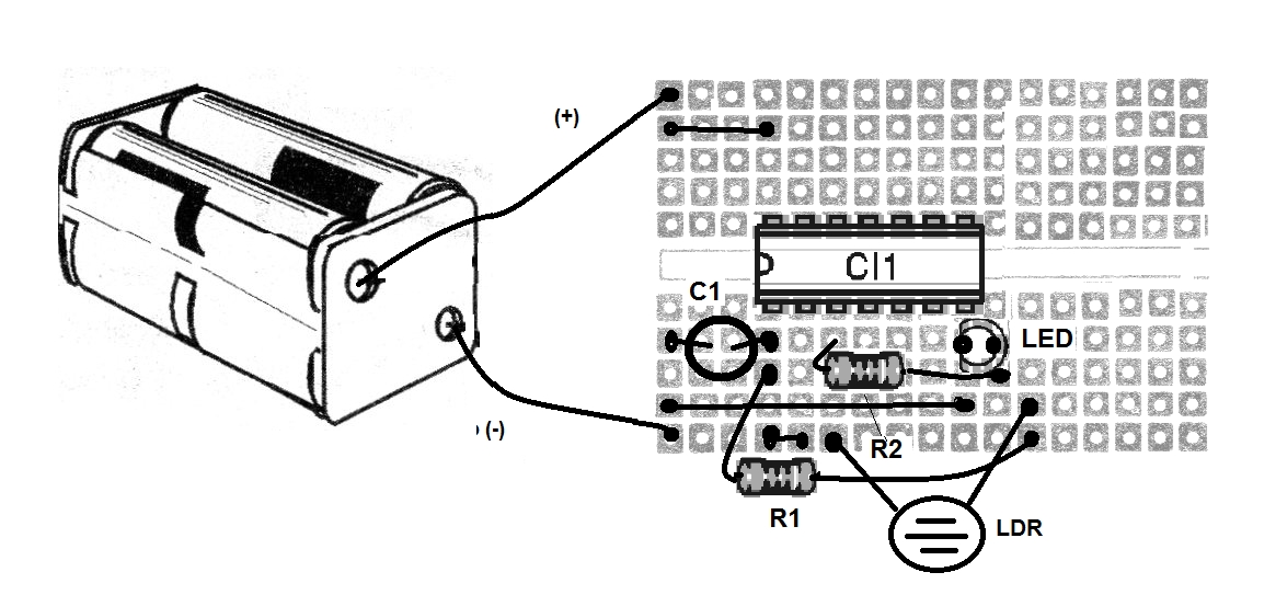
When assembling, it is important to observe the position of the integrated circuit and to dock it, do it very carefully so that all the pins are aligned with the holes. When we press the integrated circuit all the pins must fit effortlessly.
Also note the position of the LED and the polarity of the electrolytic capacitor.
Material list
CI-1 - 4093 - integrated circuit
LED1 - common
LDR - Common LDR
R1 - 10 k ohm - resistor - brown, black, orange
R2 - 1 k ohm - resistor - brown, black, red
C1 - 4.7 uF at 22 uF - electrolytic capacitor
B1 - 6 V - 4 batteries
Several:
Protoboard, batteries holder, wires, etc.


