
With this circuit it is possible to light fluorescent lamps from 3 to 40 W, even those already weakened to function in the normal installation, using ordinary batteries.
The explanation with less power is in the circuit that generates a very high voltage, but the available current is small given the capacity of the batteries used.
This circuit can be used in an emergency lighting system, in signaling and other applications. The power can come from medium or large batteries, or from a 12V battery. Small batteries should not be used, as high consumption of the device will cause them to run out quickly.
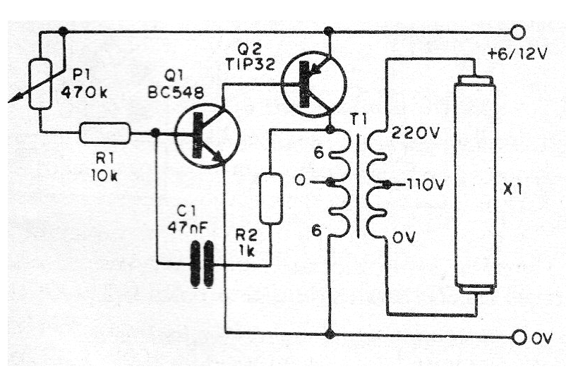
In figure 1 we have the complete diagram of the inverter.
In figure 2 we have the bridging of terminals.
23Figure 2 - Mounting suggestion using a terminal bridge
The transformer is of the type used in small power supplies with primary winding of 110 V or 220 V and secondary of 6 to 12 V with current of 200 to 500 mA. The lamp can have power from 5 to 40 W, but will not light up at maximum brightness.
The power transistor must be fitted with a heat radiator and the assembly can be installed in a small plastic housing. Be careful not to touch the wires that go to the lamp, as high voltage can cause unpleasant shocks.
Material list
Q1 - BC548 - NPN general purpose transistor
Q2 - TIP32 - PNP power transistor
P1 - 470 k ohms - trimpot
T1 - Transformer - see text
X1 - Fluorescent lamp from 5 to 40 W
R1 - 10k ohms x 1/8 W- resistor - brown, black, orange
R2 - 1 k ohms x 1/8 W - resistor - brown, black, red
C1-47 nF- ceramic or polyester capacitor
Miscellaneous: terminal strip, mounting box, wires, solder, etc.


