
In this very simple experiment with LDR, we show how this component can control a LED in an experimental passing alarm or brightness control.
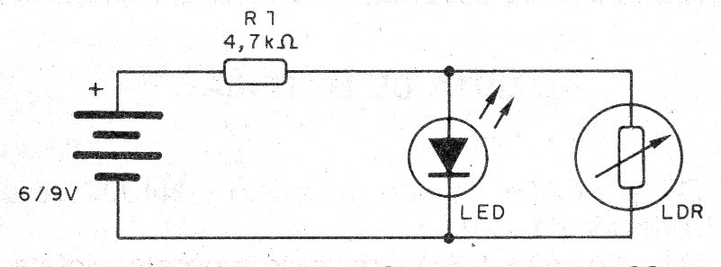
In the circuit shown, an LDR is connected in parallel with an LED to divert its current.
Thus, when the LDR is in the dark and therefore with maximum resistance, all the current goes through the LED that lights up at the maximum brightness.
When we illuminate the LDR, its resistance decreases and the current can pass through it, being diverted from the LED.
Depending on the degree of illumination, the current through the LED may be insufficient to light it and it will be turned off.
We can use the circuit to demonstrate the operating principle of a passing alarm.
In figure 1 we have the complete control circuit.
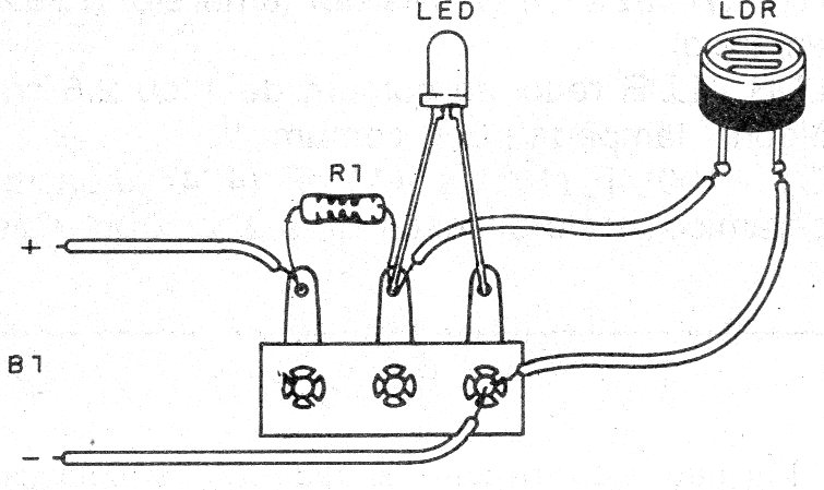
In figure 2 we show how to implement the assembly on a terminal strip, although it can also be done in a solderless board.
The power can be supplied with 4 small batteries or a 6 to 12 V supply.
Any common LDR can be used and the LED can be any size or color, you may only need to change R1 for better performance.
Material list
LDR - round common LDR
LED - LED common
R1 - 4k7 ohms x 1/8 W - resistor - yellow, violet, red
B1 - 6 to 12 V - batteries or power supply
Several:
Terminal strip, battery holder, wires, solder, etc.


