
When we first launched an FM micro-transmitter in Brazil, giving the printed circuit board a printed coil, we could not imagine that the 60,000 copies of the magazine in which we did it would be exhausted within a few days. Subsequently, we released other versions of micro-transmitters, always with great success, but even so, we believe that many readers of the new generations (and even of the old ones), have not yet performed this type of assembly.
This article is from 1986.
That's why our project, in a way reminiscent of the "old days", is an excellent micro-FM transmitter. With it, you can broadcast your voice to upcoming FM radios (up to 50 meters or more), playing a flying reporter, secret agent, or using it in recordings or representations, without the need for cumbersome microphone wire.
The circuit operates with only 2 batteries (3V) and the microphone used is electret which is a guarantee of excellent sensitivity. Improvements compared to the original design (Scorpion), guarantee an excellent performance of this transmitter.
Assembly
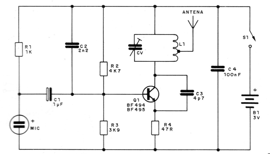
In Figure 1 we have the complete diagram of the pairing, observing that the transistor used may be either BF494 or BF495.
The design of the life-size printed circuit board, as well as the identification of the connection terminals of the two-terminal electret microphone, are given in figure 2.
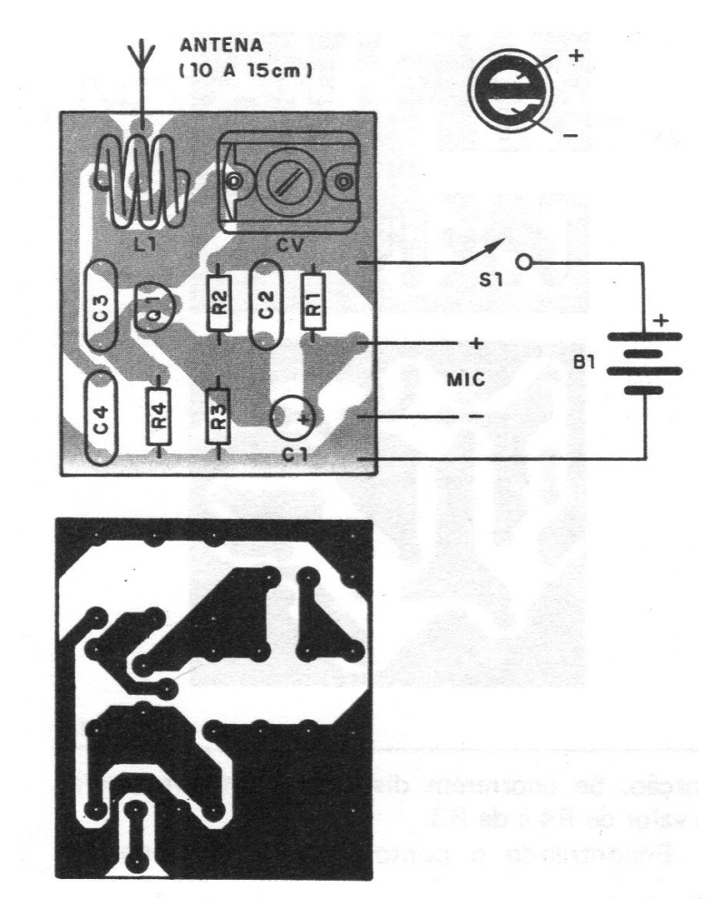
The set can be installed later in a plastic box. Do not use a metal housing to prevent the circuit from becoming unstable. The antenna is a piece of hard wire approximately 5 to 15 cm.
The coil L1 is wrapped in a pencil and is formed by 4 turns of common or thick enameled hard wire (18 to 22), with outlet in the second turn. Also note the position of the porcelain or plastic trimmer (with change of plate), with the external armature on the side of the connection at S1. If there is a reversal, the circuit may become unstable, especially for adjustment.
Test and Use
Connect a nearby FM receiver to a half-volume at a frequency where there are no stations. Using a plastic or wooden wrench (especially for coil adjustment), turn the CV screw until you pick up the strongest signal from the transmitter.
We say the stronger because more than one signal can be picked up.
Step away, talking into the microphone and retouching the receiver's tune, to check the range. If you have difficulty adjusting, remove the bobbin and wind it up with one less or more turn.
Do not talk to the FM at full volume and very close, because an acoustic feedback (microphone) appears in the form of a loud whistle.
Material list
Q1 - BF494 or BF495 - RF transistor
MIC - Two-terminal electret microphone
L1 - Coil (see text)
B1 - 3 V- two small batteries
R1 - 1k x 1/8 W - resistor (brown, black, red)
R2 - 4k7 x 1/8 W - resistor (yellow, violet, red)
R3 - 3k9 x 1/8 W - resistor (orange, white, red)
R4 - 47 ohm x 1/8 W - resistor (yellow, violet, black)
C1 - 1 uF x 6 V or more - electrolytic capacitor
C2 - 2n2 (222) - ceramic capacitor
C3 - 3p9 or 4p7 - ceramic capacitor (disk or plate)
C4 - 100 nF (104) - ceramic capacitor
S1 – On-Off switch
Miscellaneous: printed circuit board, mounting box, wires, solder, stand for 2 small batteries, etc.


