
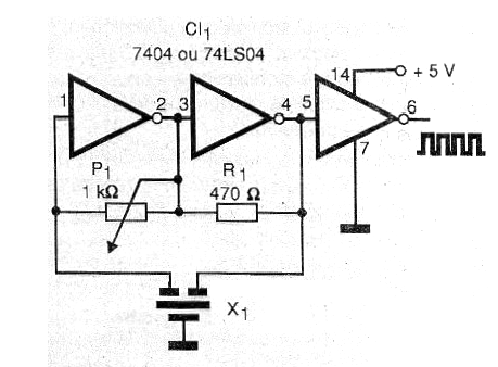
This circuit uses as standard of frequency a ceramic filter of the type found in FM radios, in the stages of intermediate frequency (FI). We can use this oscillator for the calibration of FM radios, as clock for digital circuits, or as the basis for an experimental short wave transmitter.
Remember that, because it is a TTL circuit, its power must be made with an exact voltage of 5 volt. The only adjustment the circuit needs is in the trimpot to obtain the oscillation point. In figure 1 we have the complete diagram of the oscillator.
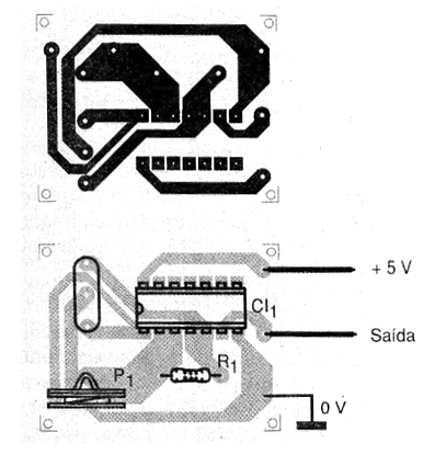
The arrangement of the components on a printed circuit board is shown in figure 2.
Three of the 6 inverters available on 7404 or 74LS04 integrated circuits are used. The other three inverters can be used in other applications since they have independent operation. Consumption of the device is low, requiring a current of a few tens of milliamps and the output consists of a rectangular signal with approximately 5 volts of amplitude.
If we connect to the output of this circuit a small antenna we will have a small transmitter with a few meters of reach. This transmitter can be used in the practice of telegraphy. Signal modulation can be done by applying an audio signal via isolation capacitor to pin 3 or 4 of the integrated circuit.
The resistor 1 / 8W and any ceramic filter for 10.7 MHz of 3 terminals can be tried in this circuit. To prove it, simply inject the signal into an FM receiver or try to tune this signal into a nearby short-wave receiver at the corresponding frequency.
MATERIAL LIST
Semiconductors:
CI-1 - 7404 or 74LS04 - TTL integrated circuit
Resistors:
R1 - 470 ohm x 1 / 8W - yellow, violet, brown
P1 - 1 k ohm - trimpot
Several:
X1 - 10.7 MHz ceramic filter
Printed circuit board, wires, solder, 5 volt source, etc.


