
Sounds and ultrasounds can be generated with the circuit shown in figure 1.
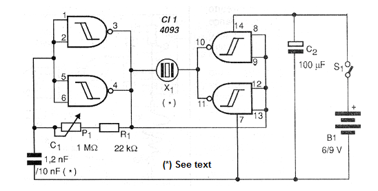
What we have is a counter-phase oscillator / amplifier that feeds a common high-impedance piezoelectric transducer.
Some of these transducers, such as those used in tweeters, have a frequency response good enough to reach the ultrasound range up to about 25 kHz.
Thus, we have two possibilities of use for the device: using common piezoelectric capsules with lower frequency response, we generate sounds. The potentiometer or trimpot P1 is then adjusted to obtain the highest yield.
On the other hand, using a piezoelectric tweeter, from which the internal transformer has been removed and connected directly to the transducer, we reduce the value of C1 and generate ultrasound.
The applications for the two cases are interesting:
a) Sounds
• Warning or alarm systems
• Scaring mosquitoes
• Audio generator
b) Ultrasounds
• Scare animals (puppies, etc.)
• Dog calls
• Generator for physics experiments
Figure 2 shows a printed circuit board for implementation of this circuit.
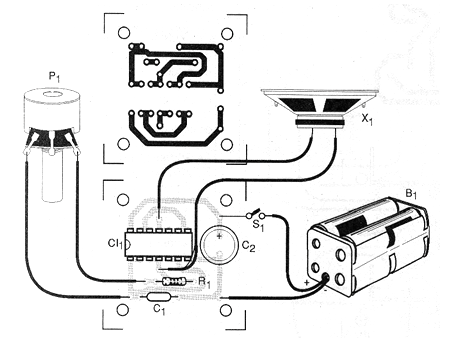
To generate ultrasound, turn the power supply on and set P1 until the sound becomes sharp until it disappears, ie out of earshot.
If you have an oscilloscope or frequency meter, you can use it to determine the frequency of oscillations.
Material list
CI-1 - 4093 - CMOS integrated circuit
Resistors: (1/8 W, 5%)
R1 - 22 k ohms - red, red, red
P1 - 1 M ohms - trimpot
Capacitors:
C1-1,200 pF (ultrasound); 10 nF - sounds
C2 - 100 uF x 12 V - electrolytic
Several:
S1 - Single switch
X1 - Transducer - see text
B1 - 6 to 12 V - batteries, battery or power supply
Printed circuit board, mounting box, battery holder or battery connector, wires, solder, etc.


