
In another article we published around 1986 again it surprised its readers with an interesting gift: the ultra-miniaturized printed circuit board for the assembly of an audio micro-amplifier. Being able to be powered with voltages 3 and 12 V, this small amplifier provided power in the range of 100 mW to close to 1 watt with excellent next quality.
In an improved version, but still "micro", we present an amplifier that will surely please readers who have not set up, or who wish to "repeat" that project.
Our amplifier also operates with voltages between 3 and 12 V and provides the same power range, which can be used to boost signals from small radios, such as a turntable or intercom, or on the bench in various equipment tests.
Assembly
In figure 1 we have the complete diagram of the micro-amplifier.
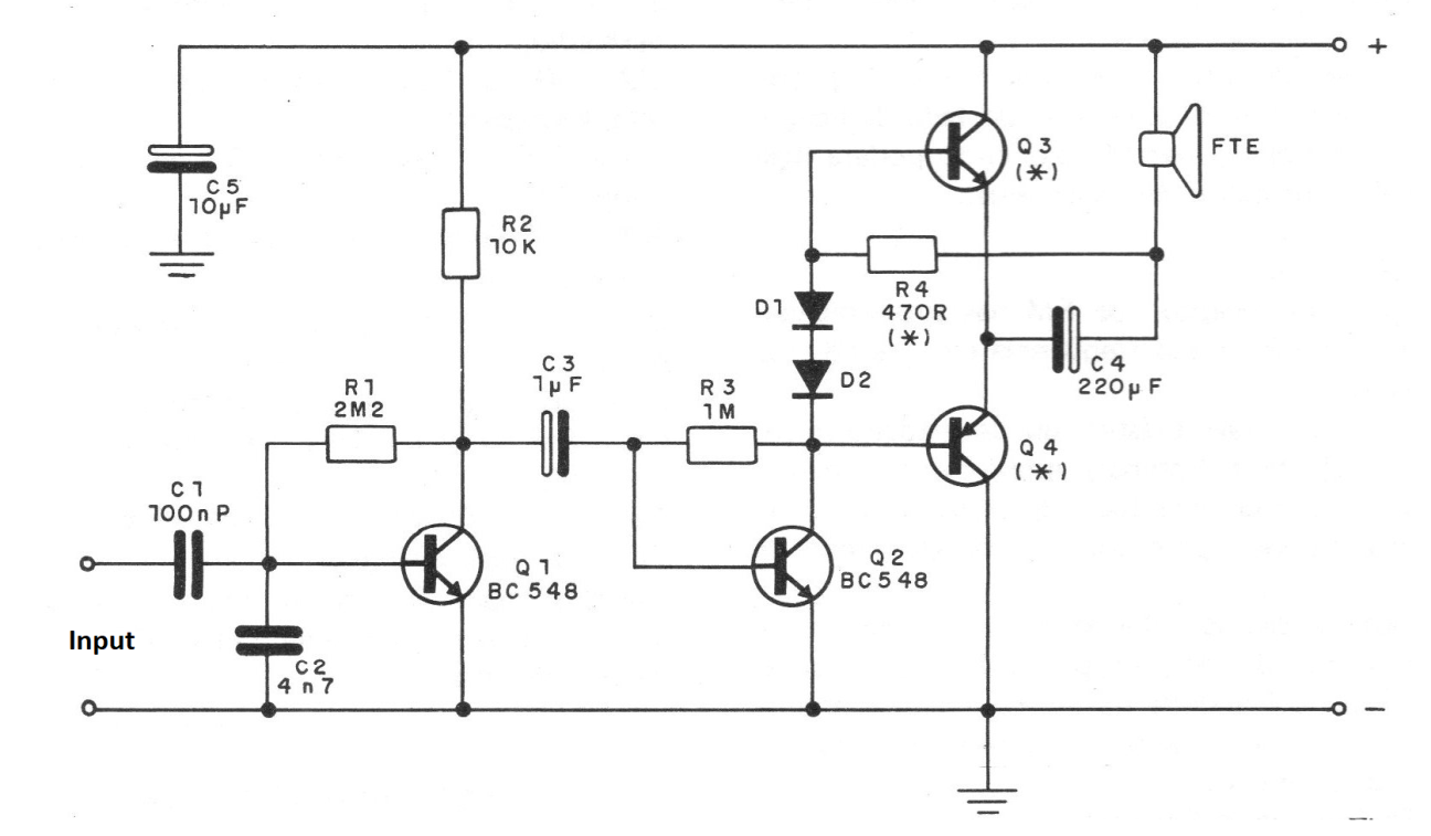
The transistors Q3 and Q4 must be chosen according to the supply voltage, as follows:
3 Volts and 6 Volts
Q3 = BC237, BC238, BC239, BC547, BC548 BCS49, BC337, BC338
Q4 = BC557, BC557, BC559, BC580, BC327, BC329
9 or 12 V:
Q3 - BC635, BC637, BC639
Q4 - BC638, BC640, BC636
The printed circuit board is shown in figure 2.
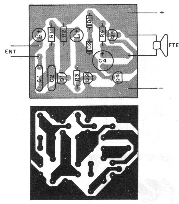
The diodes D1 and DZ can be of any type of silicon of general use, as the 1N4148, 1N4001, etc. The resistor R4 must be changed if a high rest current is noted. We can say that it can stay in the range of 470 ohms up to 2k2.
The temporary placement of a 2k2 trimpot in place of it, having in series a 470 ohm resistor for adjustment, is a solution that allows to obtain the best performance. The electrolytic capacitors must have work voltages slightly larger than the chosen supply voltage.
The resistor R3 also influences the current at rest and the performance of the amplifier, and can be changed in the range of 220 ohms to 1M5.
Test and Use
Connect the amplifier to a well-filtered source with a current rating of at least 500 mA or a set of batteries. At the output, connect a good quality 4 or 8 ohm speaker.
Apply the signal to the input. This signal can come from a turntable with crystal capsule, a crystal microphone, a radio, a tape-deck or a cassette recorder.
Obs. The article is from 1986. Other modern signal sources may be used.
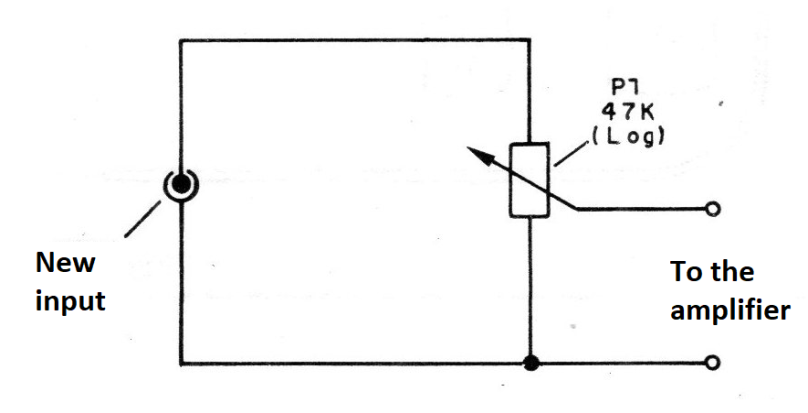
On the radio and recorder, the signal can be taken from the phone or monitor jack. In figure 3 we give the procedure to add a volume control.
Playback should come out normal and high without distortion. If distortions occur, try changing the value of R4 and R3. Finding the ideal point of operation is just to use your micro amplifier.
Mount two units to have a stereo system.
Material list
Q1, Q2 - BCS48
Q3 - View text
Q4 - View text
D1, D2-1N4148 or equivalent - silicon diodes
R2 - 2M2 x 1/8 W - resistor (red, red, green)
R2 - 10k x 1/8 W - resistor (brown, black, orange)
R3 - 1 M x 1/8 W - resistor (brown, black, green)
R4 - 470 ohm x 1/8 W - resistor (yellow, violet, brown)
C1 - 100 nF (104) - ceramic capacitor
C2 - 4n7 (472) - ceramic capacitor
C3 - 1 uF - electrolytic capacitor
C4 - 200 uF - electrolytic capacitor
C5 - 10 uF - electrolytic capacitor
Miscellaneous: printed circuit board, 4 or 8 ohm speaker, wires, power supply, volume potentiometer (see text), etc.


