
The circuit shown in figure 1 combines signals of two frequencies and can be used in instrumentation as a modulator or for multiplexing of sensor information.
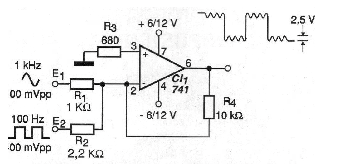
The gain of the circuit is determined by the ratio of R4 to R3 and the value of R4 can be varied according to the application and the intensity of the input signals. The way the input signals are combined, that is, their amplitudes depend on the heats of R1 and R2.
The power supply must be symmetrical and with the use of a common operational amplifier such as the 741 the cutoff frequency of the circuit is around 1 MHz. In order to combine higher frequency signals, other operational amplifiers must be used.
In figure 2 we have a suggestion of printed circuit board for this combiner.
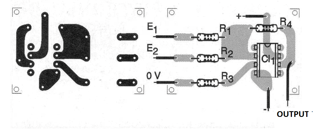
If the pinout of the integrated circuit used is other than the 741 changes in the board must be made.
MATERIAL LIST
CI-1 - 741 - operational amplifier
R1 - 1k ohm x 1/8 W - resistor - brown, black, red
R2 - 2.2 k ohm x 1/8 W - resistor - red, red, red
R3 - 680 ohm x 1/8 W - resistor - blue, gray, brown
R4 - 10 k ohm x 1/8 W - resistor - brown, black, orange
Several:
Printed circuit board, symmetrical power supply, wires, solder, etc.


