
This circuit produces low intensity discharges in those who hold the electrodes. Of course, the circuit should be used with caution, although shocks are not dangerous.
This circuit can be used in experiments in physiology and in games or electronic games.
The discharge is of low current and is therefore harmless, but caution must be exercised in its use.
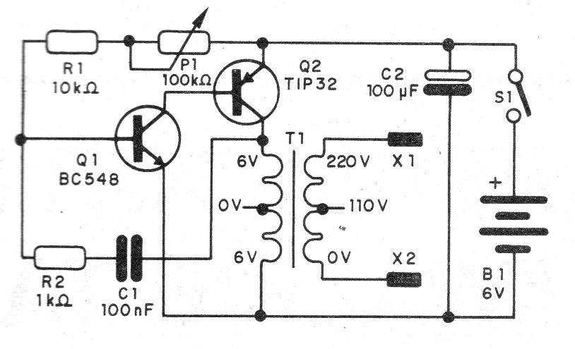
The circuit consists of an oscillator in which the low voltage signal is applied to a transformer that raises its voltage by applying it to the electrodes.
The intensity of the shock depends on the frequency and is adjusted on the potentiometer P1.
In figure 1 we have the complete diagram of the apparatus.
Since this is a very simple experimental setup, we suggest the use of a terminal strip with the arrangement shown in figure 2.
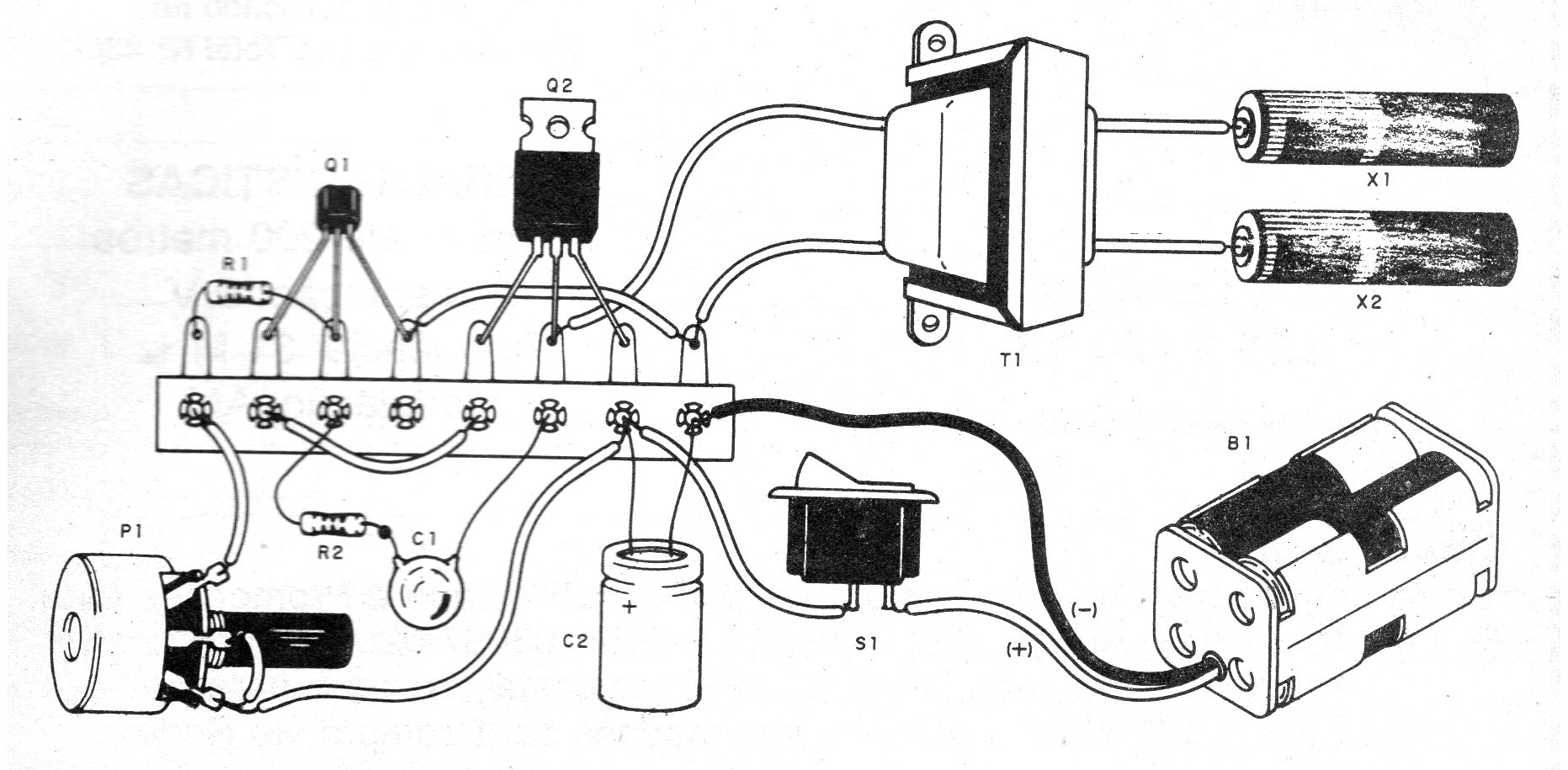
Observe the transistor and transformer positions on the assembly.
Any small transformer that has one or two windings of 5 to 12 V with a current of 100 to 300 mA can be used.
The primary can be 110 V or 220 V.
The power can be made by small, medium or large batteries.
To test, connect a neon light bulb to the output and adjust the potentiometer.
The electrodes may be two metal tubes or two spent cells that have the outer paint scraped.
Material list
Q1 - BC548 - NPN general purpose transistor
Q2 - TIP32 - PNP power transistor
T1 - transformer - see text
X1, X2 - electrodes - see text
S1 – On-Off switch
B1 - 4 batteries
P1 - 100 k ohms - potentiometer
R1 - 10 k ohms - resistor - brown, black, orange
R2 - 1 k ohms - resistor - brown, black, red
C1 - 100 nF - ceramic or polyester capacitor
C2 - 100 uF x 12 V - electrolytic capacitor
Several:
Terminal strip, battery holder, wires, mounting box, solder, etc.


