
The circuit shown in figure 1 illuminates a high performance white LED when there is no light, ie when the LDR stops receiving ambient light.
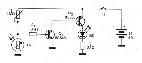
Of course, it has a key to turn off the circuit that we no longer need light, even in the absence of ambient light.
We then have a circuit in which an LDR, upon ceasing to receive light, allows P1 to polarize the base of saturating transistor Q1. With the saturation of Q1, the transistor Q2 is also polarized and with this leads the current that illuminates the LED.
The trigger point of the circuit, ie its sensitivity is set at P1.
The circuit can be powered with 4 small batteries and installed in a small plastic box.
In figure 2 we give a suggestion of a terminal strip mounting that is a version recommended to the less experienced readers.
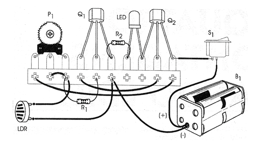
It is clear that more experienced readers can make the assembly on printed circuit board and, if it is for demonstration, in an array of contacts.
The R1 resistor can be reduced in case the LED accepts a larger current. The minimum recommended value is 22 ohms.
Material list
Q1 - BC548 - NPN general purpose transistor
Q2 - BC558 - general purpose PNP transistor
LED - high performance white LED
LDR - common round LDR
P1 - 1 M ohms - trimpot
R1 - 10 k ohms x 1/8 W - resistor - brown, black, orange
R2 - 100 ohms x 1/8 W - resistor - brown, black, brown
S1 - Single switch
B1 - 6 V - 4 small batteries
Several:
Printed circuit board, battery holder, mounting box, wires, solder.


