
When the light no longer strikes the LDR of the circuit of Figure 1, the oscillator takes effect producing an acute sound which basically depends on the value of C1. Larger values produce more bass sounds.
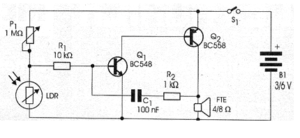
The sensitivity is set in the trimpot or potentiometer of 1 M ohms and the circuit can be powered by two or four small batteries.
The loudspeaker can be any type with 5 to 10 cm in diameter and impedance of 4 or 8 ohms.
In figure 2 we have the assembly of the alarm in a terminal bridge.
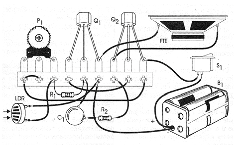
Readers with more features can either mount them on a printed circuit board or in a matrix of contacts.
Material list
Q1 - BC548 or equivalent - general purpose NPN transistor
Q2 - BC558 or equivalent - general purpose PNP transistor
LDR - round common LDR
P1 - 1 M ohms - trimpot or potentiometer
R1 - 10 k ohms x 1/8 W - resistor - brown, black, orange
R2 - 1 k ohms x 1/8 W - resistor - brown, black, red
C1 - 100 nF - ceramic or polyester capacitor
FTE - 4 or 8 ohms - 5 to 10 cm common speaker
S1 - Single switch
B1 - 3 or 6 V - two or four small batteries
Several:
Terminal strip, battery holder, mounting box, wires, solder, etc.


