
This simple intermittent can power lamps (or LEDs) with currents up to 1 A with 12 V supply. We can use it in signage, decoration, warning systems, etc.
The circuit is quite simple because it uses only an integrated circuit and a power transistor as a base, and the assembly can be performed in a very compact way for mobile applications.
The power transistor can easily control lamps up to 1 A. The frequency of the light pulses can be adjusted over a wide range of values. There are no critical components, which facilitates their practical realization.
How it works
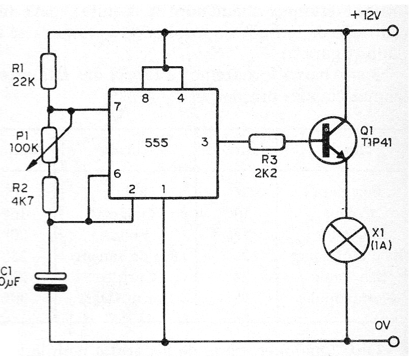
An integrated circuit 555 is connected as a low-frequency cable, directly driving a power NPN transistor. The frequency is determined by the potentiometer, R1, R2 and C1. See in the math section of the website how to calculate the frequency of this circuit.
Assembly
In figure 1 we have the complete diagram of the intermittent and in figure 2 the suggestion of printed circuit board for the assembly.
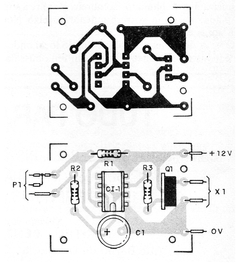
The transistor must be provided with a heat radiator. The circuit also works with lamps and 6V supply.
To test the circuit, simply turn on the power and set the frequency at P1. Do not use bulbs of more than 1 A.
Material list
CI-1 - 555 - integrated circuit
Q1- TIP41 - NPN power transistor
P1- 100 k ohm - trimpot
C1- 10 uF x 16 V or more - electrolytic capacitor
R1 - 22k ohm x 1/8 W - resistor - red, red, orange
R2 - 4.7 k ohm x 1/8 W- resistor - yellow, violet, red
R3 - 2.2k ohm x 1/8 W- resistor - red, red, red
X1- 12 V lamp up to 1 A
Various: printed circuit board, heat radiator for Q1, wires, solder, etc.


