
One way to get an accurate frequency signal is to use a quartz crystal-controlled oscillator. For this purpose we can have circuits that both make use of transistors and integrated circuits.
The circuit shown in figure 1 can generate rectangular (logic-compatible) signals between 100 kHz and 2 MHz serving as clock for microprocessors, microcontrollers and the like.
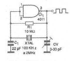
We use a 4011 port, but any port that can be configured as an inverter can be used. The power supply can be made with voltages from 5 to 15 V and the capacitors must be ceramic. The signal produced is close to the rectangle and can be amplified digitally (buffered) by the other ports of the same IC.
In figure 2 we have a suggestion of printed circuit board, although, in most cases, the circuit is part of a more complex configuration included in the same board.
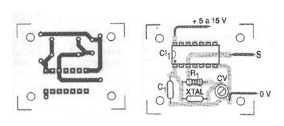
The trimmer is used to set the starting point for the oscillator to start up easily when it is switched on. This trimmer also slightly adjusts the frequency by its action on the internal resonances of the crystal. A suggestion for those who want lower frequencies using this oscillator is to divide the signal by values that are powers of 2 based on a 4020, as shown in figure 3.
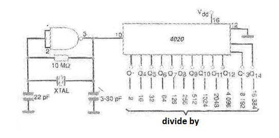
As shown in the figure, applying the signal at the input of this IC, the frequency will be divided by powers of 2, with the possibility of dividing by up to 16 384. With this, frequencies of a few hertz can be obtained with a crystal of greater frequency, without problems.
Two or more 4020 may be cascaded to obtain extremely low frequencies from crystals.
Material list
C I-1 - 4011 or equivalent - CMOS integrated circuit
XTAL - 100 kHz crystal at 10 MHz
R1 - 10 M ohm x 1/8 W - resistor
C1 - 22 pF - ceramic
C2-3-30 pF trimmer
Several:
Printed circuit board, wires, etc.


