
It is not necessary to tell about the utility of a signal gun for those who know how to use this instrument. You can have a good signal gun with few components and the circuit board given in this article.
We describe the assembly of a simple signal injector, with only two transistors, that works with both 1 and 2 small cells. An astable multivibrator that oscillates in the audio track has a harmonic that extends to the bands of the high frequencies, which allows its use in radio.
Calibration, adjustment and fault finding in the most diverse electronic devices can be made with the help of this instrument. The circuit provides for the use of any type of NPN silicon transistors of general use.
ASSEMBLY
The complete circuit is given in figure 1 and in reality the components are not at all critical.
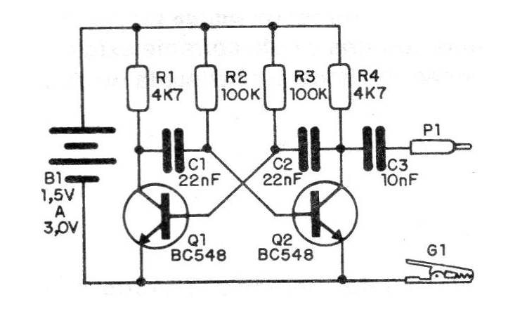
The capacitor C1 may have values between 15 and 47 nF, while the resistors R1 and R4 may be between 3k3 and 6k8. The resistors R2 and R3 may have values between 47 k and 150 k and the capacitor C3 may have values between 4 n7 and 22 nF.
Ceramic or polyester types can be used for the capacitors and the resistors can be 1/8 or ¼ W.
The compact printed circuit board is shown in figure 2.
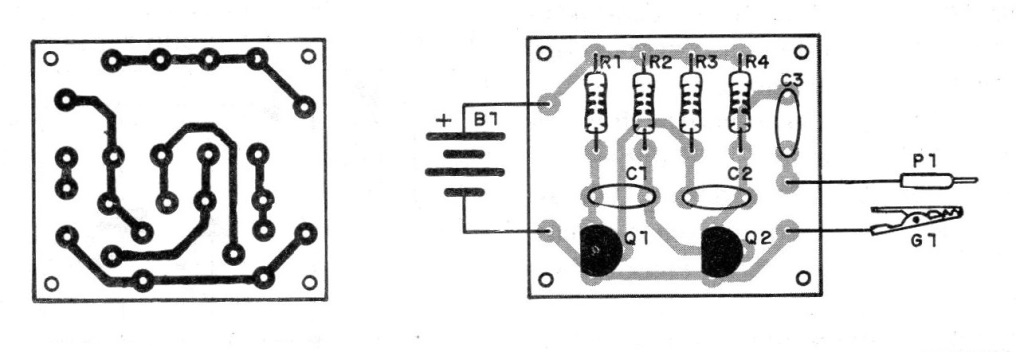
The tip of the injector is a small common nail that can be welded directly onto the plate. In figure 3 we suggest the installation in a base of thick cardboard or wood that will be installed in a plastic box.
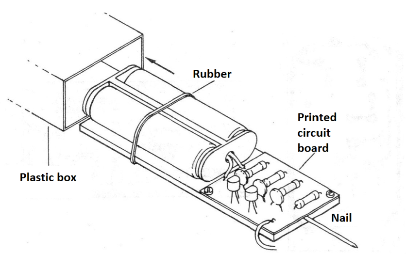
The batteries are fastened with a rubber band and the main switch is optional.
To connect the batteries, simply place them in the holder. The consumption of the unit is very low, which guarantees enormous durability even if we leave the unit on for hours at a time.
Test and Use
To test the injector simply apply your signal to the input of any audio amplifier.
To use, we must connect the clamp to the ground or ground of the tested device and apply the probe to the input and output of each step, when there must be sound reproduction.
MATERIAL LIST
Q1, Q2 - BC548 or any commonly used silicon NPN
C7, C2-22 nF - ceramic or polyester capacitor (223)
C3 - 10 nF - ceramic or polyester capacitor (103)
R1, R4 - 4k7 - resistor (yellow, violet, red)
R2, R3 - 100k - resistors (brown, black, yellow)
B1 - 1,5 or 3 V - 1 or 2 small batteries
P1 - Probe (see text)
G1 - Alligator Claw
Miscellaneous: printed circuit board, support for one or two batteries, mounting box, wires, soldering etc.


