
The gain of the amplifier shown in Figure 1 depends on the strength of the input signal. With weak signals the gain is greater and with strong signals the gain decreases.
This gain can typically range from somewhere around 1 for strong signals (with amplitude close to the supply voltage) to 50,000 for mute signals of the order of microvolts.
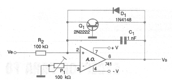
Utilities:
• Interface sensors that have gained a very wide range, tailoring their response to the processing circuit.
• Modify the dynamic range of a signal for transmission and then retrieve it in control interface and acquisition of data in industrial and research applications.
• Operate as a log gain preamp for microphones and other sensors.
• Modify the dynamic fading of an audio signal for radio transmission with higher throughput.
Constructive Details:
In figure 2 we have a suggestion of printed circuit board for the assembly of the logarithmic amplifier. We note that the layout depends very much on the type of signal that will be worked on.
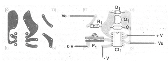
For small-intensity audio signals, inputs and outputs must be shielded.
The configuration shown is for operating amplifiers of all types. For operation with very low signal voltages, both the transistor and the diode must be germanium. The power supply must be symmetrical. It is also important to remember that when working with audio signals the lines of input and output of these signals must be made with shielded wires.
List of materials:
Semiconductors:
CI - 741 or any operational amplifier
Q1 - 2N2222 - general purpose transistor
D1 - 1N4148 - general purpose diode
Resistors: (5%)
R1 - 100 k ohms x 1/8 W
P1 - 100 k ohms - trimpot
Capacitor:
C1 - 1 nF - ceramic
Several:
Printed circuit board, symmetrical source, wires, solder, etc.


