
The purpose of this project is educational, showing how a transistor works with a simple assembly in a contact array of 170 points.
We describe a simple experiments that can be implemented in elementary and middle level courses and serve as an introduction to technology. With it, we learn how a transistor works.
Level: Fundamental, middle and initiation
Purpose: To show how a PNP transistor works in the same previous circuits in which we use an NPN (MIN653). In this case, we will only mount the version of the touch switch, leaving the others to the experimenters.
Explanation
The direction of current flow in a PNP transistor is opposite to that of an NPN transistor, as shown in the figure.
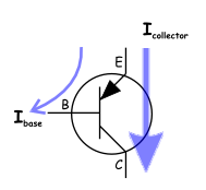
Thus, while in a NPN transistor, to conduct we apply a positive voltage, in a PNP transistor the voltage must be negative, that is, we connect the base to the negative or 0 V of the source. Once polarized, the transistor conducts, but the current has different direction, which implies in the inversion of the LED.
The PNP transistors can be found with the same characteristics of the NPN and a common type, equivalent to the BC548 is the BC558 that we will use in this project. So, holding the wires, the small current that flows through our body is enough to polarize the transistor and cause it to drive, turning on the LED.
Assembly
In Figure 2 we have the touch switch diagram using the PNP transistor.
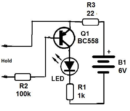
The assembly made in the 170 point contact array is shown in figure 3.
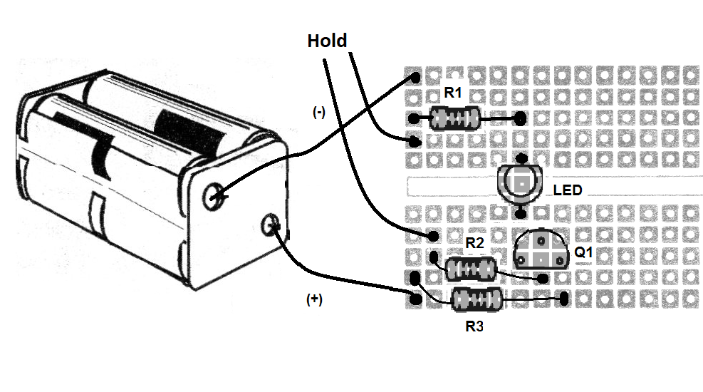
When assembling, note that we reverse the polarity of the LED, the position of the transistor and the polarity of the battery holder.
Used material
Q1 - BC558 - PNP transistor
LED - LED common
R1 - 1 k ohm - resistor - brown, black, red
R2 - 100 k ohm - resistor - brown, black, yellow
R3 - 22 ohm - resistor - red, red, black
B1 - 4 batteries
Several:
Matrix of contacts, support of batteries, wires, etc.


