
The circuit, shown in Figure 1, triggers a relay when the light incident on a sensor (LDR) is cut off.
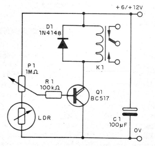
This circuit is also very sensitive, which means a very small current in the LDR besides the possibility of working with very weak light sources. In fact, even imperceptible levels of light for the human eye are enough to power this circuit. The base is also a single BC517 transistor that powers a relay.
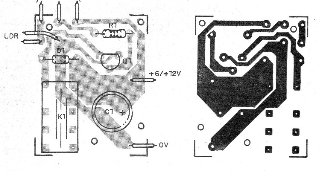
P1 makes the sensitivity adjustment and the power can be made with 6 or 12 V depending on the relay. The printed circuit board for this design is shown in figure 2.
A capacitor can be added between the base and the emitter of the transistor in order to reduce its speed. This capacitor can have values between 220 nF and 2 200 uF.
Material list
Q1 - BC517 - Darlington transistor
LDR - Common LDR
D1 - 1N4148 - general purpose diode
K1 - 6 or 12 V relay
P1 - 1 M ohm - potentiometer
R1 - 100 k ohm - resistor - brown, black, yellow
C1 - 100 uF - electrolytic capacitor
Several:
Printed circuit board, wires, solder, etc.


