
This experimental transmitter can be used as didactic assembly in telecommunication courses, sending the tone-modulated telegraph signals to an FM or VHF receiver placed at a distance of up to 200 meters.
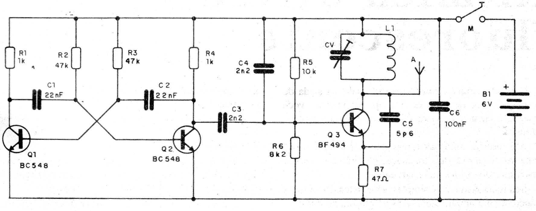
The circuit can operate in the range of 50 to 130 MHz, depending only on the coil used. The table below shows the approximate number of turns for the desired frequencies.
5 to 7 turns - 50 to 70 MHz
4 turns - 80 to 100 MHz
2 turns - above 100 MHz
The pitch modulation is made by an astable multivibrator whose frequency depends on two resistors R1 and R2, which can be changed over a wide range of values.
As antenna can be used a piece of hard wire of 10 to 60 cm in length or even a telescopic antenna.
The power can be made by voltages of 6 to 9 V obtained from source, batteries or battery.
In figure 1 we have the complete diagram of the transmitter.
Ideally for assembly, a printed circuit board is used, although the circuit will also work with less conventional mounting techniques such as the contact array or even a bridge of insulated terminals.
In figure 2 we have the arrangement of the components for a bridging of terminals.
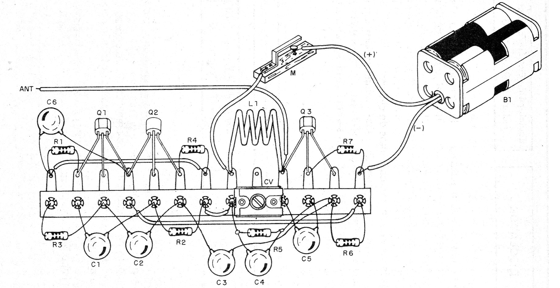
The capacitors must all be of the ceramic type and the connections should be kept as short as possible.
CV is a common trimmer that can be both old porcelain type and modern plastic with capacitance maximum of 5 to 30 pF.
To test, simply press the handler with the device connected next to a receiver tuned to free frequency and adjust the trimmer to pick up the signal with maximum intensity.
Material list
Q1, Q2 - BC548 - general purpose NPN transistors
Q3 - BF494 or 2N2222 - RF transistor or switching
L1 - Coil - see text
CV - trimmer - see text
B1 - 6 to 9 V - batteries, power supply or battery
R1 and R4 - 1k ohms x 1/8 W- resistor - brown, black, red
R2 3 R3 - 47 k ohms x 1/8 W - resistors - yellow, violet, orange
R5 - 10 k ohms x 1/8 W - resistor - brown, black, orange
R6 - 8k2 ohms x 1/8 W- resistor - gray, red, red
R7 - 47 ohms x 1/8 W- resistor - yellow, violet, black
C1 and C2 - 22 nF - ceramic capacitors
C3 and C4 - 2n2 - ceramic capacitors
C5 - 5p6 - ceramic capacitor
C6 - 100 nF - ceramic capacitor
Several:
Terminal strip or printed circuit board, battery holder, wires, solder, etc.


