
You press a switch and an LED lights up for a time that both depends on the value of resistor R1 and capacitor C1. You can use this circuit as a simple timer for response times in school competitions or chess matches or other applications with times up to 1 minute.
Another possibility of use is common apparatus to show the charge and discharge of capacitors, verifying if they are in good condition.
In figure 1 we have the complete diagram of the apparatus and its assembly based on a small strip of insulated terminals.
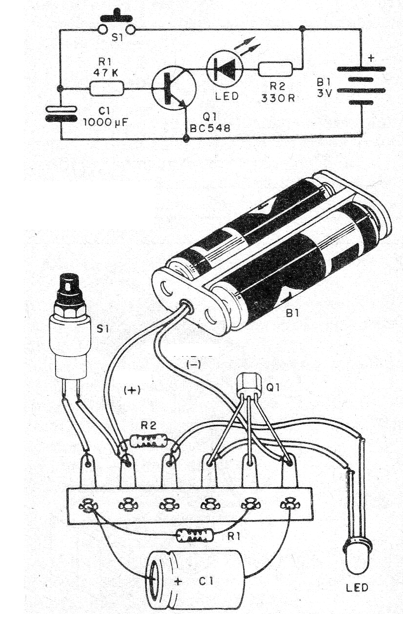
The transistor can be of any general purpose NPN type and the LED can also be of any color or type. The time depends on C1 which can have values between 100 uF and 4 700 uF. The resistor can have values between 10k and 100k. Times longer than 1 minute can be obtained with 4 700 uF and 100k.
To use, just press S1 for a moment. The LED will light up and will stay on for as long as it depends on C1 and R1. When the LED is off, the consumption of the appliance becomes insignificant. The circuit will also run on 6 V, changing R2 to 1k.
Material list
Q1 - BC548 - NPN general purpose transistor
LED - common red LED
S1 - Pressure switch NA
B1- 3 or 6 V - 2 or 4 small batteries
C1- 100 to 4 700 uF x 6 V or more - electrolytic capacitor
R1 - 47 k ohm x 1/8 W - resistor - yellow, violet, orange
R2 - 330 ohm x 1/8 W - resistor - orange, orange, brown
Miscellaneous: battery holder, terminal bridge, wires, solder, etc.


