
This amplifier can be used as a design base that requires little audio power, such as toys, radios, intercoms, earphone systems etc.
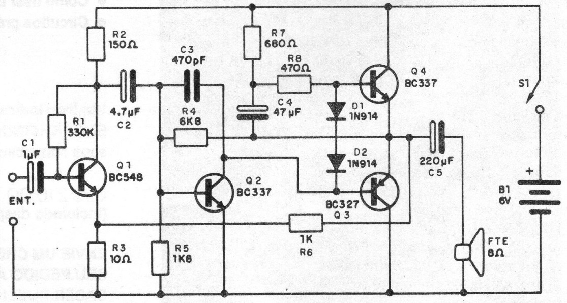
The power is made with only 6V and the charge can be a speaker of 8 ohm, of at least 10 cm for better quality of sound. In figure 1 we have the diagram of the amplifier.
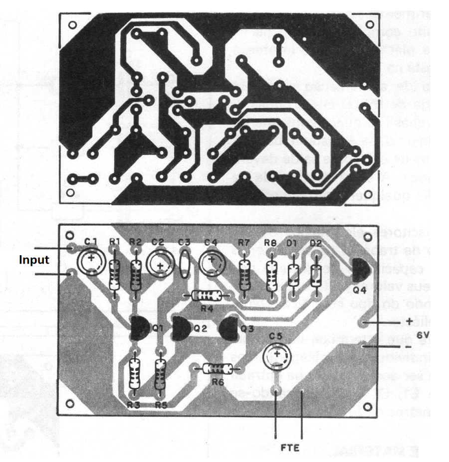
In figure 2 we have the micro board that allows the use of the circuit with ease even in small spaces.
Complementary symmetry output provides excellent sound quality and good performance, which means good battery life. If source is used, it should have good filtering.
The volume control (not shown) can be a 1ook potentiometer connected to the input. The resistors are all 1/8 or ¼ W, the electrolytic capacitors are for 6 V or more and the other capacitors are ceramic or polyester.
Equivalent of 1N914 diode is 1N4148.
MATERIAL LIST
Q1 - BC548 - NPN transistor
Q2, Q3 - BC337 - NPN transistors
Q4 - BC327 - PNP transistor
D1, D2 - 1N914 or equivalent - general purpose diodes
S1 – On-Off switch
B1 - 6 V - 4 batteries or power supply
R1 - 330 k x 1/8 W - resistor (orange, orange, yellow)
R2 - 150 ohm x 1/8 W - resistor (brown, green, brown)
RS - 10 ohm x 1/8 W - resistor (brown, black, black)
R4 - 6k8 x 1/8 W - resistor (blue, gray, red)
R5 - 1k8 x 1/8 W - resistor (brown, gray, red)
R6 - 680 ohm x 1/8 W - resistor (blue, gray, brown)
R7 - 470 ohm x 1/8 W - resistor (yellow, violet, brown)
RB - 1k x 1/8 W - resistor (brown, black, red)
C1 - 1 uF x 6 V - electrolytic capacitor
C2 - 4.7 UF x 6 V - electrolytic capacitor
CS - 470 pF - ceramic capacitor
C4 - 47 uF x 6 V - electrolytic capacitor
C5 - 220 uF x 6 V - electrolytic capacitor
Miscellaneous: speaker, printed circuit board, battery holder or power supply, wires, input jack etc.


