
The purpose of this didactic project is 170 points protoboard is to show how an astable multivibrator can operate at a high frequency and applying its signals in a transducer, we can get sounds.
Explanation
As we know, in an astable multivibrator, the two transistors are constantly changing state and with that, a signal is produced. This signal, as we call a current that varies in intensity, in the case of a flashing light with LEDs, as we described in other projects, is very low frequency and with this, they turn on and off at a very low speed.
But by switching the capacitors and removing the LEDs, we can make the frequency or speed with which the transistors turn on and off much higher, in the hundreds, thousands and even millions of times a second. When the frequency is in the range of 16 to 15 000 Hertz (16 to 15 000 times per second) the signals are in what is called an audible track, or audio.
These signals, if applied to an appropriate transducer, ie a device that converts electrical signals into sounds, such as a loudspeaker or a piezoelectric capsule, produce audible sounds. The sound will be all the louder the higher the signal frequency.
In our case, we have chosen appropriate capacitors of values that, together with the base resistors of the transistors, will result in signals of the audio track. Applying these signals to the piezoelectric transducer will produce a continuous sound.
Assembly
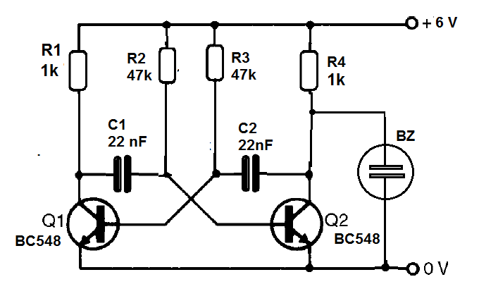
In figure 1 we have the complete diagram of our astable multivibrator that operates in the audio range.
The assembly is made in the protoboard with the arrangement shown in figure 2.
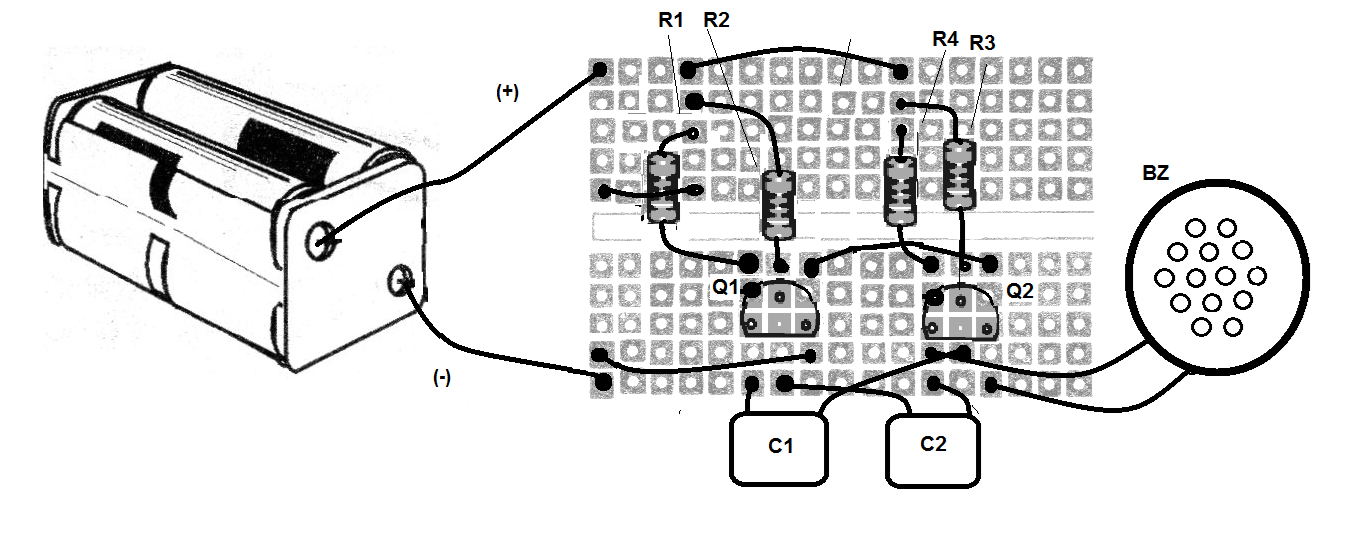
When assembling, observe the position of the transistors and the polarity of the batteries supplying the circuit. The transducer is connected to the collector of one of the transistors, where we remove the signal for playback.
Transducers of various types, without the oscillator, can be experienced, varying greatly the volume of the obtained sound according to the type. These transducers can be found in toys, electronic applications and other places, being used in this project.
Note that this signal can also be removed from the collector of the other transistor. Observe carefully the values of the resistors that are given by the colored bands.
Material list
Q1, Q2 - BC548 - NPN transistors
R1, R4 - 1k ohm - resistor - brown, black, red
R2, R3-47 k ohm - resistor - yellow, violet, orange
C1, C2-22 or 47 nF - electrolytic capacitors
B1 - 6 V - 4 batteries
BZ - Piezoelectric transducer
Several:
Protoboard, batteries holder, wires, etc.


