
This circuit blocks an interfering signal of a certain frequency that may be hindering its reception of medium or short waves. The circuit is connected in series with the receiver and the antenna, being adjusted to obtain signal blocking.
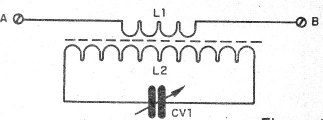
The circuit consists of a tuned rejection stage, connected between the external antenna and the receiver in order to block an interfering signal.
The coils have windings according to the frequency, according to the table given below:
550 - 1 600 kHz - L1 = 10 turns L2 = 80 turns
1 600 to 4 MHz - L1 = 10 turns L2 = 40 turns
4 MHz to 12 MHz - L1 = 6 turns L2 = 20 turns
12 MHz to 20 MHz - L1 = 4 turns L2 = 12 turns
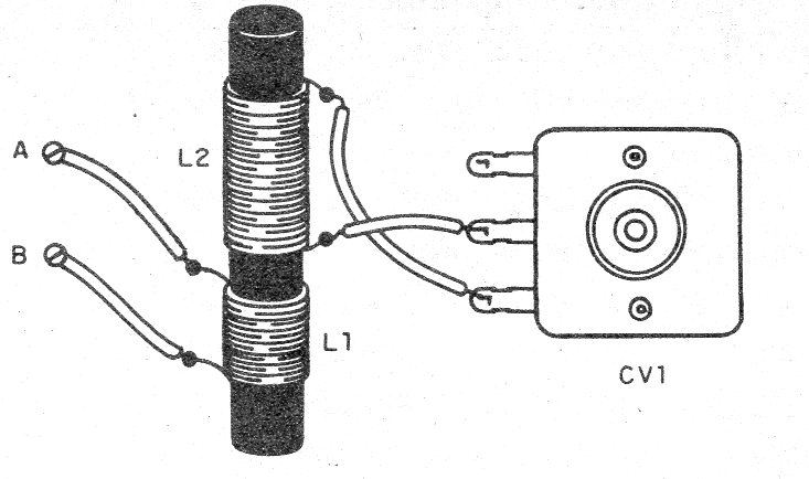
The core is a ferrite rod 12 to 20 cm long and 0.8 to 1.2 cm in diameter.
The variable capacitor can be removed from some out-of-use AM radio.
In figure 1 we have the simple diagram of the filter.
In figure 2 we have the assembly aspect. The circuit can be installed in a plastic box.
To use, connect the circuit in series with the antenna input of the receiver.
Material list
L1, L2 - Coils - see text
CV - variable capacitor - see text
Several:
Box for mounting, enameled wires 28 to 32, wires, solder, etc.


