
If you find it difficult to listen to distant shortwave stations on your source-fed radio due to interference, or if your analog television picture for the VHF range shows lines and drizzle at certain times, when someone in the vicinity turns on an appliance , it's a sign that you need a filter.
The filter shown resolves any interference problems coming to your AM, OC or TV through the power grid. For interferences that come through space, in the form of waves, this filter does not fit, so it will be interesting to consider this hypothesis if the filter does not work as expected.
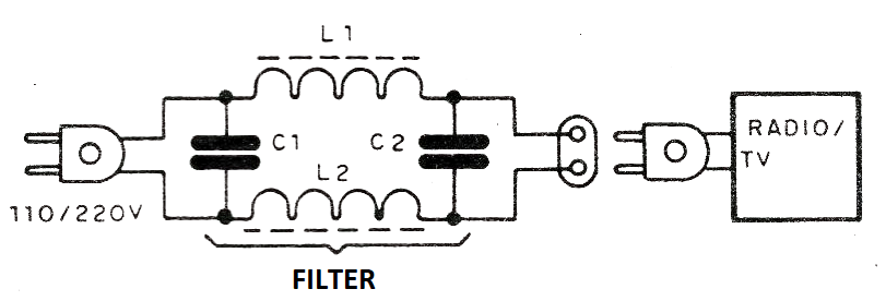
The connection of the filter is made by interleaving it between the mains (outlet) and the interfering device or between the mains socket and the interfering device, as shown in figure 1.
The assembly is simple and can be carried out in a plastic or metal box, as shown in figure 2.
23Figure 2 - Layout of the filter components
The coils are formed by 50 or more turns of common wire or 22 AWG in a ferrite rod approximately 10 cm long and 1 cm in diameter. The capacitors must be of polyester with at least 250 V of working voltage if the network is 110 V, and at least 400 V if the network is 220 V.
The circuit consists of a low-pass filter where the capacitors short-circuit the interfering signals. This filter will work well in eliminating interfering signals above 100 kHz.
Material list
L1, L2 - Coils- see text
C1, C2- 100 nF- polyester capacitors - see text
Miscellaneous: ferrite rods, wires, solder, mounting box, plug and socket.


