
Two pieces of uncovered wire or two metal plaques are used as sensors in the circuit of figure 1.
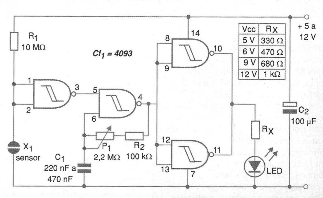
When the resistance between the sensor elements falls below 3 M ohm (value determined by R1) the LED flashes at a frequency that can be set in the trimpot.
The circuit can be used to monitor the filling of water reservoirs, leaks, rain start and other applications involving humidity or water to drive. With an additional power stage the circuit can be used to activate a "sonalert" sound indicator. Blinking frequency is determined by C1.
Circuit power can be supplied with voltages from 6 to 12 V from batteries, batteries or power supply. However, for safety reasons, if used power supply it must be of the isolated type of transformer network.
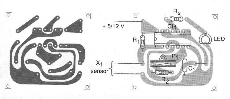
The Rx resistor that determines the current in the LED depends on the supply voltage and has its values given by the table next to the diagram. In figure 2 we have a suggestion of printed circuit board for the assembly of this indicator circuit.
A reduction of the sensitivity can be achieved with the decrease of R1.
MATERIAL LIST
CI-1 - 4093 - CMOS integrated circuit
LED - red LED or any other color
R1 - 10 M ohm x 1/8 W - resistor - brown, black, blue
R2 - 100 k ohm x 1/8 W - resistor - brown, black, yellow
Rx - see text - 1/8 W - resistor
C1 - 220 nF at 1 uF - ceramic or polyester capacitor
C2 - 100 uF x 16 V - electrolytic capacitor
Several:
Printed circuit board, wires, solder, sensor, etc.


