
This photometer can be used to measure light intensities or to compare ink tones and in many other applications with high precision is not necessary.
We can also use it in various experiments in the physics lab.
The circuit shown in figure 1 uses a 0-1 mA or 0-200 uA microammeter to indicate the intensity of light incident on the LDR.
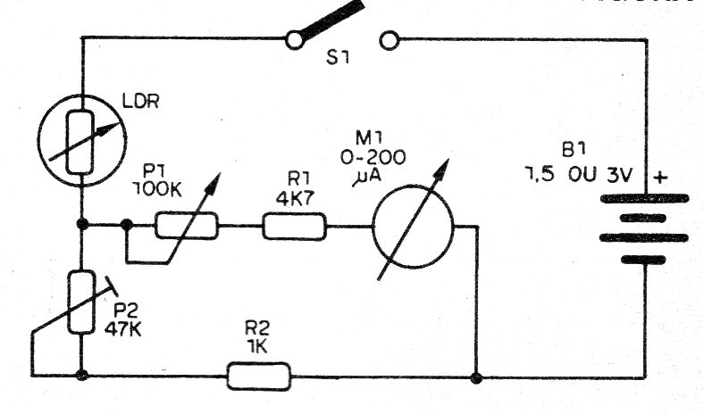
The circuit can be mounted on a terminals strip, because it is a very simple configuration.
The arrangement of the components on a terminal strip is shown in figure 2.
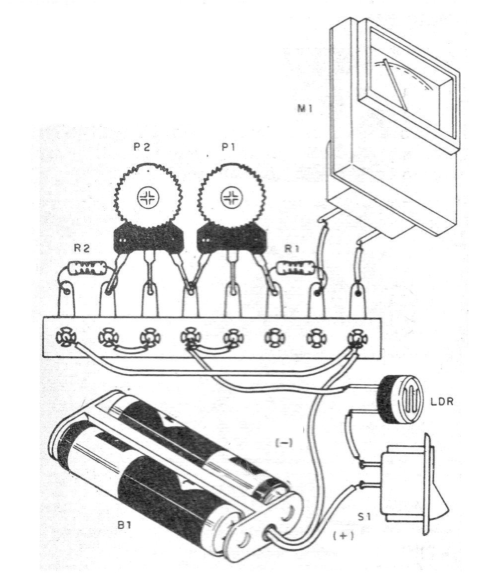
The resistors are 1/8 W with any tolerance and the instrument can have full scale of 200 uAa 1 mA.
Instruments of this type can be availed of old sound equipment where they were used as VU-meter.
The circuit has two settings.
Initially place the 47k P1 trimpot in the center of the setting and illuminate the LDR.
Then adjust P2 so that the instrument does not exceed the end of the scale.
Then set P1 again according to the range of light to measure.
Once the adjustments have been made, the reader can draw up a brightness scale for your instrument based on a commercial photometer.
Material list
LDR - Common LDR
M1 - 0-200 mA instrument or 0-1 mA
P1 - 47 k ohms - trimpot
P2 - 100 k ohms - trimpot
B1 - 1.5 V to 3 V - 1 or 2 batteries
R1 - 4k7 ohms - resistor - yellow, violet, red
R2 - 1 k ohms - resistor - brown, black, red
Several:
Terminal strip, battery holder, mounting box, wires, solder, etc.


